SG_FSE_SiplaceHF_HF3_00193901-05_eng.pdf - 第311页
S tudent Guide SIPLACE HF/HF3 Edition 09/2005 Contents 1 Chapter T able of Content s 7 TWIN-Head . . . . . . . . . . . . . . . . . . . . . . . . . . . . . . . . . . . . . . . . . . . . . . . . . . . . . . . . . 1 7.1 Ove…
1 - 110
Student Guide SIPLACE HF/HF3
6 Collect &Place-Head / DLM2 Edition 09/2005
110
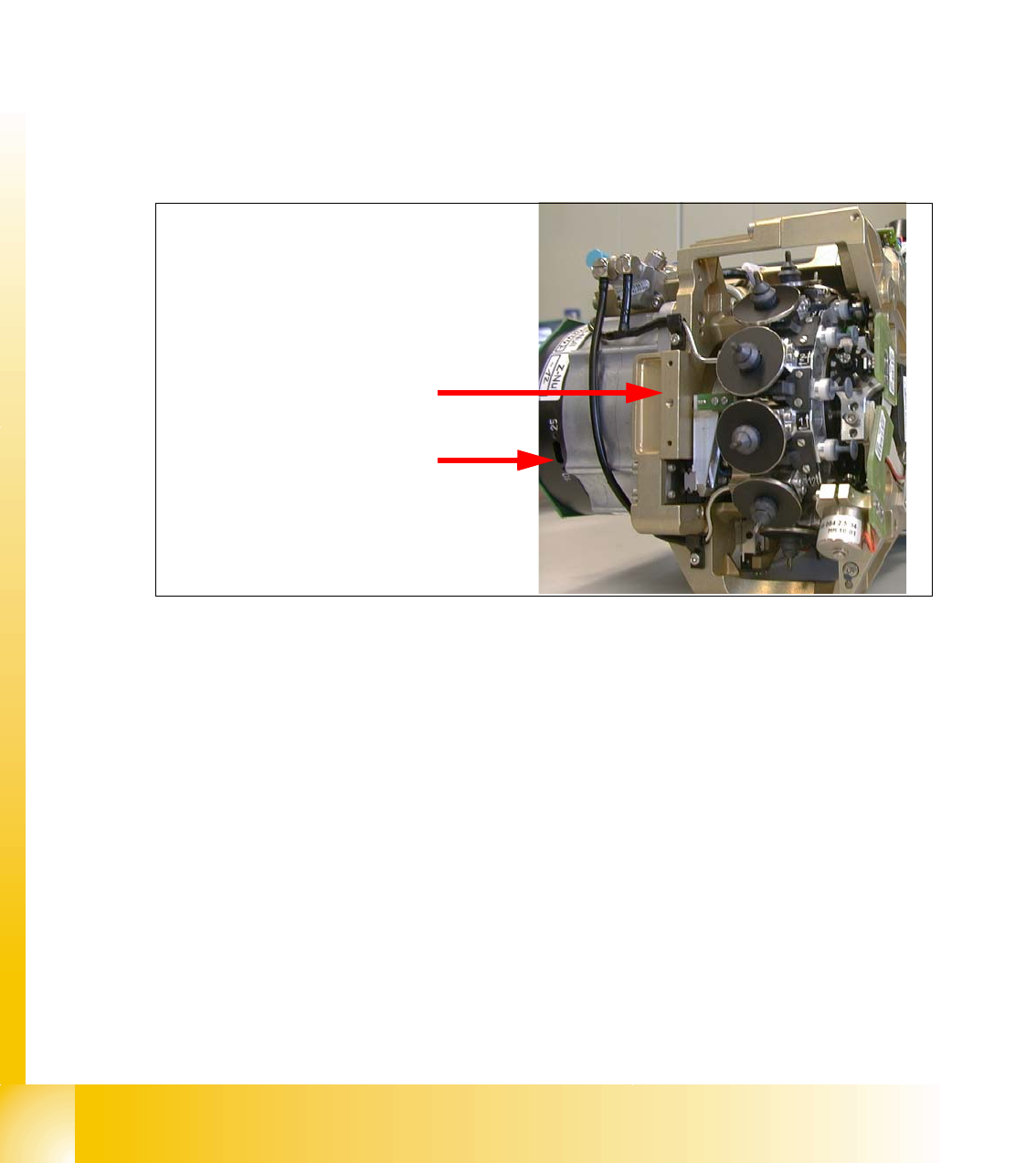
6.8.6 Zeropoint correction star axis DLM 2
The switch for the track resolution must be checked case in case of a replacement of the C&P
head.
– On HS-60 and S-27 HM this switch is set to
10 x.
– On the SIPLACE HF this switch is set to
25x.
Please observe the following items in case of manual setting of the zero point correction:
– The procedure for the setting of the zero point gauge stays the same.
– The attachement point for the star axis gauge is situated a little lower, so that the pin for cen-
tering segment 1 might not snap in the segment guidance at once. In that case the Z-axis must
be pulled downward until the pin snaps in the segment guidance.
Fig. 6.8 - 7 DLM 2 switch setting
Attachment point for
zero point gauge
Switch 10x / 25x for
track signal resolution

Student Guide SIPLACE HF/HF3
Edition 09/2005 Contents
1
Chapter
Table of Contents
7 TWIN-Head. . . . . . . . . . . . . . . . . . . . . . . . . . . . . . . . . . . . . . . . . . . . . . . . . . . . . . . . . 1
7.1 Overview. . . . . . . . . . . . . . . . . . . . . . . . . . . . . . . . . . . . . . . . . . . . . . . . . . . . . . . . . . . . . . . . . . . . . . . 1
7.1.1 Technical Data TWIN- Head . . . . . . . . . . . . . . . . . . . . . . . . . . . . . . . . . . . . . . . . . . . . 2
7.1.2 Parts on the TWIN- Head . . . . . . . . . . . . . . . . . . . . . . . . . . . . . . . . . . . . . . . . . . . . . . 3
7.1.2.1 Vacuum generator TWIN- Head. . . . . . . . . . . . . . . . . . . . . . . . . . . . . . . . . . . . . . 4
7.2 Reference Run TWIN-head . . . . . . . . . . . . . . . . . . . . . . . . . . . . . . . . . . . . . . . . . . . . . . . . . . . . . . . . 5
7.2.1 Reference run at Z axis . . . . . . . . . . . . . . . . . . . . . . . . . . . . . . . . . . . . . . . . . . . . . . . . 6
7.2.2 Reference run at D- axis . . . . . . . . . . . . . . . . . . . . . . . . . . . . . . . . . . . . . . . . . . . . . . . 7
7.2.3 Vacuum check. . . . . . . . . . . . . . . . . . . . . . . . . . . . . . . . . . . . . . . . . . . . . . . . . . . . . . . 8
7.2.4 Height reference run . . . . . . . . . . . . . . . . . . . . . . . . . . . . . . . . . . . . . . . . . . . . . . . . . . 9
7.3 Pick up and Placement Cycle of the Twin Head . . . . . . . . . . . . . . . . . . . . . . . . . . . . . . . . . . . . . . 11
7.3.1 General . . . . . . . . . . . . . . . . . . . . . . . . . . . . . . . . . . . . . . . . . . . . . . . . . . . . . . . . . . . 11
7.3.2 Placement principle Twin-head . . . . . . . . . . . . . . . . . . . . . . . . . . . . . . . . . . . . . . . . . 12
7.3.3 Prepare pick up process module 1 . . . . . . . . . . . . . . . . . . . . . . . . . . . . . . . . . . . . . . 12
7.3.3.1 Pick up component module 1. . . . . . . . . . . . . . . . . . . . . . . . . . . . . . . . . . . . . . . 13
7.3.4 Prepare pick up process module 2 . . . . . . . . . . . . . . . . . . . . . . . . . . . . . . . . . . . . . . 14
7.3.4.1 Pick up component module 2. . . . . . . . . . . . . . . . . . . . . . . . . . . . . . . . . . . . . . . 14
7.3.5 Component centering module 1 and 2 . . . . . . . . . . . . . . . . . . . . . . . . . . . . . . . . . . . 15
7.3.6 Prepare placement 1st component . . . . . . . . . . . . . . . . . . . . . . . . . . . . . . . . . . . . . . 16
7.3.6.1 Place 1st component . . . . . . . . . . . . . . . . . . . . . . . . . . . . . . . . . . . . . . . . . . . . . 16
7.3.7 Prepare placement 2nd component . . . . . . . . . . . . . . . . . . . . . . . . . . . . . . . . . . . . . 17
7.3.7.1 Place 2nd component. . . . . . . . . . . . . . . . . . . . . . . . . . . . . . . . . . . . . . . . . . . . . 17
7.4 Adjustments . . . . . . . . . . . . . . . . . . . . . . . . . . . . . . . . . . . . . . . . . . . . . . . . . . . . . . . . . . . . . . . . . . . 19
7.4.1 Description of the switches and boards on the TWIN-Head. . . . . . . . . . . . . . . . . . . 19
7.4.1.1 Head interface . . . . . . . . . . . . . . . . . . . . . . . . . . . . . . . . . . . . . . . . . . . . . . . . . . 19
7.4.1.2 Vision board . . . . . . . . . . . . . . . . . . . . . . . . . . . . . . . . . . . . . . . . . . . . . . . . . . . . 21
7.4.1.3 CAN Processorboard 16 Bit . . . . . . . . . . . . . . . . . . . . . . . . . . . . . . . . . . . . . . . . 22
7.4.1.4 Head adapter Twin Head . . . . . . . . . . . . . . . . . . . . . . . . . . . . . . . . . . . . . . . . . . 23
7.4.1.5 TWIN-Head main board . . . . . . . . . . . . . . . . . . . . . . . . . . . . . . . . . . . . . . . . . . . 24
7.4.1.6 Vision control board "IC camera" . . . . . . . . . . . . . . . . . . . . . . . . . . . . . . . . . . . . 25
7.4.2 Parameter and Calibrations. . . . . . . . . . . . . . . . . . . . . . . . . . . . . . . . . . . . . . . . . . . . 26
7.4.2.1 Overview calibration steps and parameter in the Sitest . . . . . . . . . . . . . . . . . . . 26
7.4.3 Parameter TWIN-head . . . . . . . . . . . . . . . . . . . . . . . . . . . . . . . . . . . . . . . . . . . . . . . 27
7.4.4 Calibrate D-Axis. . . . . . . . . . . . . . . . . . . . . . . . . . . . . . . . . . . . . . . . . . . . . . . . . . . . . 29
7.4.4.1 Manual Calculation of the ZPC D-axis . . . . . . . . . . . . . . . . . . . . . . . . . . . . . . . . 30

1 - 2
Student Guide SIPLACE HF/HF3
Contents Edition 09/2005
2
7.4.5 Calibrate head height. . . . . . . . . . . . . . . . . . . . . . . . . . . . . . . . . . . . . . . . . . . . . . . . . 30
7.4.6 Zero calibration for pressure regulator on the TWIN-Head . . . . . . . . . . . . . . . . . . . . 31
7.4.6.1 Zero calibration vacuum generator. . . . . . . . . . . . . . . . . . . . . . . . . . . . . . . . . . . 31
7.4.6.2 Check the Zero calibration of the vacuum generator . . . . . . . . . . . . . . . . . . . . . 32
7.4.6.3 Calibrate closed vacuum . . . . . . . . . . . . . . . . . . . . . . . . . . . . . . . . . . . . . . . . . . 32
7.4.6.4 Check the pressure tightness of the vacuum system. . . . . . . . . . . . . . . . . . . . . 33
7.4.6.5 Check the "Air kiss" pressure . . . . . . . . . . . . . . . . . . . . . . . . . . . . . . . . . . . . . . . 34
7.4.7 Calibrating the Twin Head . . . . . . . . . . . . . . . . . . . . . . . . . . . . . . . . . . . . . . . . . . . . . 34
7.4.8 Mechanical adjustment the incremental encoder Z-axis . . . . . . . . . . . . . . . . . . . . . . 35
7.5 Nozzle changer. . . . . . . . . . . . . . . . . . . . . . . . . . . . . . . . . . . . . . . . . . . . . . . . . . . . . . . . . . . . . . . . . . 1
7.5.1 Nozzle changer for TWIN- head . . . . . . . . . . . . . . . . . . . . . . . . . . . . . . . . . . . . . . . . . 1
7.5.2 Position and assembly the nozzle changer . . . . . . . . . . . . . . . . . . . . . . . . . . . . . . . . . 2
7.5.2.1 Position. . . . . . . . . . . . . . . . . . . . . . . . . . . . . . . . . . . . . . . . . . . . . . . . . . . . . . . . . 2
7.5.2.2 Assembly nozzle changer magazine . . . . . . . . . . . . . . . . . . . . . . . . . . . . . . . . . . 2
7.5.2.3 Description of the functions . . . . . . . . . . . . . . . . . . . . . . . . . . . . . . . . . . . . . . . . . 3
7.6 Axis control . . . . . . . . . . . . . . . . . . . . . . . . . . . . . . . . . . . . . . . . . . . . . . . . . . . . . . . . . . . . . . . . . . . . 5
7.6.1 Overview Axis control Z- and D-Axis . . . . . . . . . . . . . . . . . . . . . . . . . . . . . . . . . . . . . 5
7.6.1.1 Overview positioning time for the TWIN- head. . . . . . . . . . . . . . . . . . . . . . . . . . . 6
7.6.2 Track signals head axes . . . . . . . . . . . . . . . . . . . . . . . . . . . . . . . . . . . . . . . . . . . . . . . 7
7.6.2.1 Test set up . . . . . . . . . . . . . . . . . . . . . . . . . . . . . . . . . . . . . . . . . . . . . . . . . . . . . . 7
7.6.3 Axis control TWIN- Head Z-axis . . . . . . . . . . . . . . . . . . . . . . . . . . . . . . . . . . . . . . . . . 9
7.6.3.1 Check the dynamic of Z-axis . . . . . . . . . . . . . . . . . . . . . . . . . . . . . . . . . . . . . . . . 9
7.6.3.2 Test setup with Axis testbox. . . . . . . . . . . . . . . . . . . . . . . . . . . . . . . . . . . . . . . . 10
7.6.3.3 Test setup with SAT-Box . . . . . . . . . . . . . . . . . . . . . . . . . . . . . . . . . . . . . . . . . . 11
7.6.3.4 Check the function of the force sensor. . . . . . . . . . . . . . . . . . . . . . . . . . . . . . . . 13
7.6.4 Axis control TWIN- Head D-axis . . . . . . . . . . . . . . . . . . . . . . . . . . . . . . . . . . . . . . . . 15
7.6.4.1 Check the dynamic of D-Axis . . . . . . . . . . . . . . . . . . . . . . . . . . . . . . . . . . . . . . . 15
7.6.4.2 Test setup. . . . . . . . . . . . . . . . . . . . . . . . . . . . . . . . . . . . . . . . . . . . . . . . . . . . . . 16