SG_FSE_SiplaceHF_HF3_00193901-05_eng.pdf - 第321页
1 - 9 S tudent Guide SIPLACE HF/HF3 Edition 09/2005 7 TWIN-Head 9 7.2.4 Height reference run With this function we check the correct nozzle type which is prog rammed. The nozzle length is ta ken to calculate the pick up …

1 - 8
Student Guide SIPLACE HF/HF3
7 TWIN-Head Edition 09/2005
8
7.2.3 Vacuum check
– After the machine is switched ON the CAN Bus prozessor will be started and therefore the
Vacuum-, Air kiss generator will be initialized. Neither vacuum or air kiss is on the nozzle.
– The Gantry axes move the TWIN-head to the reject position.
– Over the reject box the Vacuum-, Air kiss generator switch to air kiss to reject components and
check the air kiss.
– The Vacuum-, Air kiss generator is switchted to vacuum and the open vacuum threshold is
measured. (The closed vacuum threshold is taken from SITEST calibration.)
– The pressure air is adjusted to 0 bar.
– After this the height reference run started
1 - 9
Student Guide SIPLACE HF/HF3
Edition 09/2005 7 TWIN-Head
9
7.2.4 Height reference run
With this function we check the correct nozzle type which is programmed.
The nozzle length is taken to calculate the pick up and placement height for the following place-
ments.
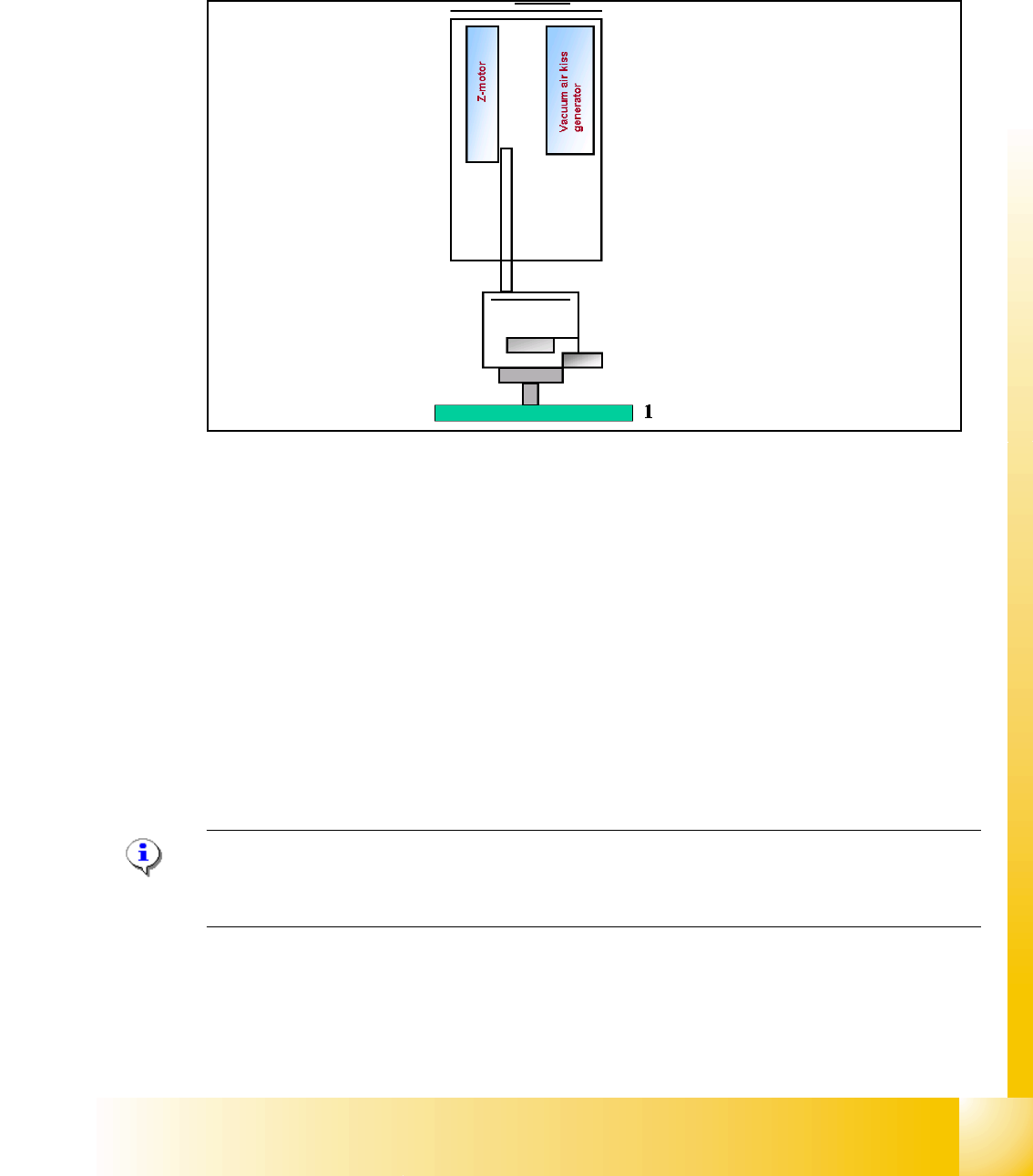
Fig. 7.2 - 4 Measure nozzle height
1. Top of fixed conveyor rail
– The gantry moves the placement heads above the fixed conveyor rail.
– The Z-Axis module 2 positioned downwards.
– The vacuum-, Air kiss generator regulate the vacuum. The reference value for closed vacuum
is calibrated in the SITEST with a standard nozzle 518.
– From the travel range of the Z-Axis is the TWIN-head height calculated referring to the nozzle
type.
– Now the same happen with module 1.
– The maximum length tolerance is 0,4 mm: If the length difference is too high an error message
is displayed.
Please Note
Both modules are measured at the same position of the PCB-Transport! This TWIN-Reference run
happen parallel to the C&P-head reference run at the other placement area.