SG_FSE_SiplaceHF_HF3_00193901-05_eng.pdf - 第322页
1 - 10 S tudent Guide SIPLACE HF/HF3 7 TWIN-Head Edition 09/2005 10 . Notes:
1 - 9
Student Guide SIPLACE HF/HF3
Edition 09/2005 7 TWIN-Head
9
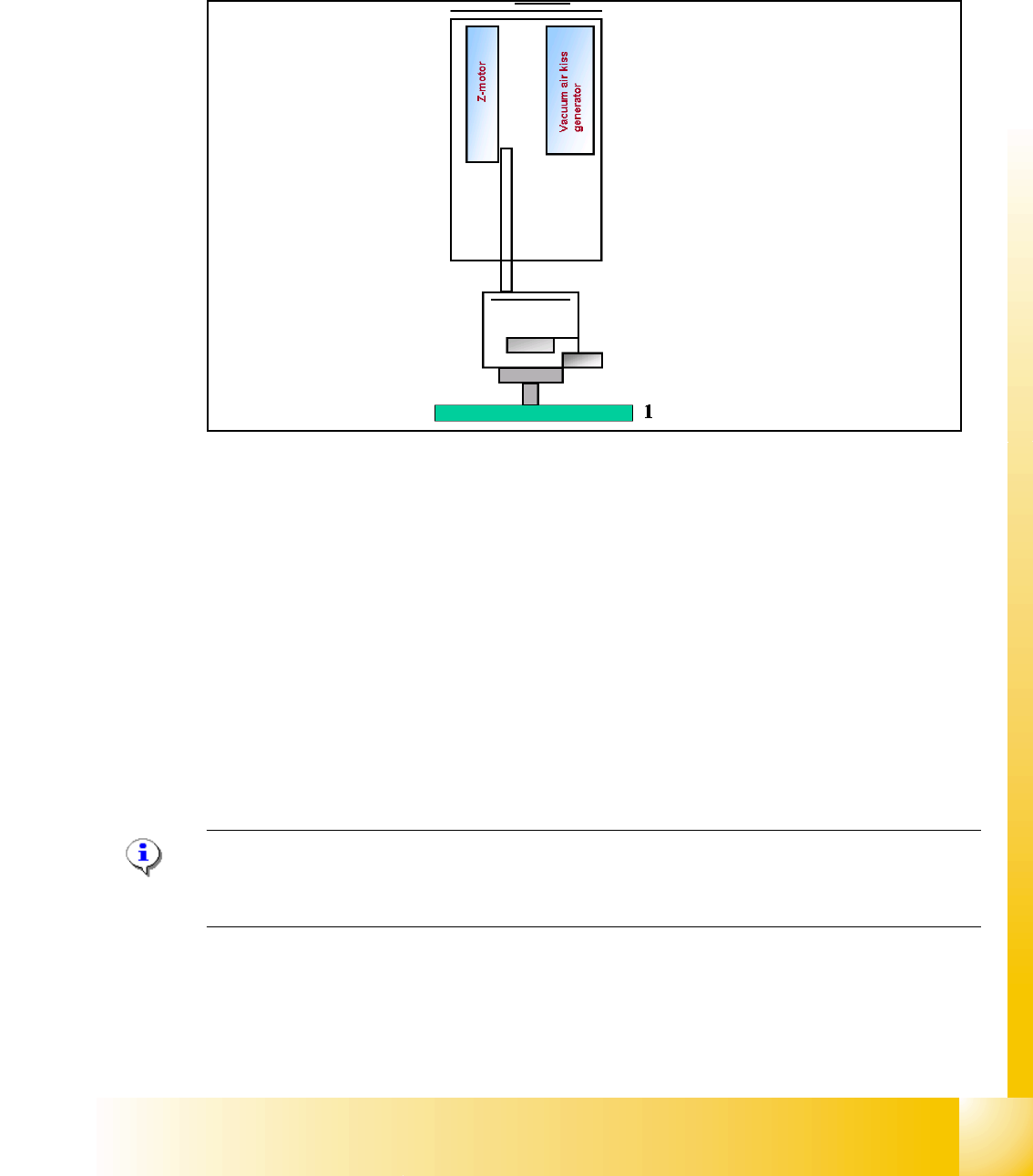
7.2.4 Height reference run
With this function we check the correct nozzle type which is programmed.
The nozzle length is taken to calculate the pick up and placement height for the following place-
ments.
Fig. 7.2 - 4 Measure nozzle height
1. Top of fixed conveyor rail
– The gantry moves the placement heads above the fixed conveyor rail.
– The Z-Axis module 2 positioned downwards.
– The vacuum-, Air kiss generator regulate the vacuum. The reference value for closed vacuum
is calibrated in the SITEST with a standard nozzle 518.
– From the travel range of the Z-Axis is the TWIN-head height calculated referring to the nozzle
type.
– Now the same happen with module 1.
– The maximum length tolerance is 0,4 mm: If the length difference is too high an error message
is displayed.
Please Note
Both modules are measured at the same position of the PCB-Transport! This TWIN-Reference run
happen parallel to the C&P-head reference run at the other placement area.
1 - 11
Student Guide SIPLACE HF/HF3
Edition 09/2005 7 TWIN-Head
11
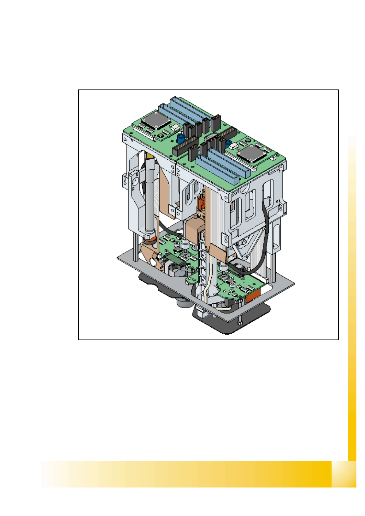
7.3 Pick up and Placement Cycle of the Twin Head
7.3.1 General
Fig. 7.3 - 1 Twin head overview
The module 2 of the TWIN Head is 180 degree mounted to module 1.
The distance between the nozzles is approximately 71 mm in X - direction.
The maximum component height is 25 mm.
Programmable placement force 0.5N – 15N,
Rotational accuracy of 0.07°, 4sigma / X- and Y- axis 35µm 4 sigma.
Improved Odd Shape Component-capabilities (components up to 200x125mm, weight of 100g)
3700 cph for large components