SG_FSE_SiplaceHF_HF3_00193901-05_eng.pdf - 第324页
1 - 12 S tudent Guide SIPLACE HF/HF3 7 TWIN-Head Edition 09/2005 12 7.3.2 Placement principle T win-head During PCB-tra nsport time wait th e gantry at t heoretical fiducial position to execute PCB-position recognition (…
1 - 11
Student Guide SIPLACE HF/HF3
Edition 09/2005 7 TWIN-Head
11
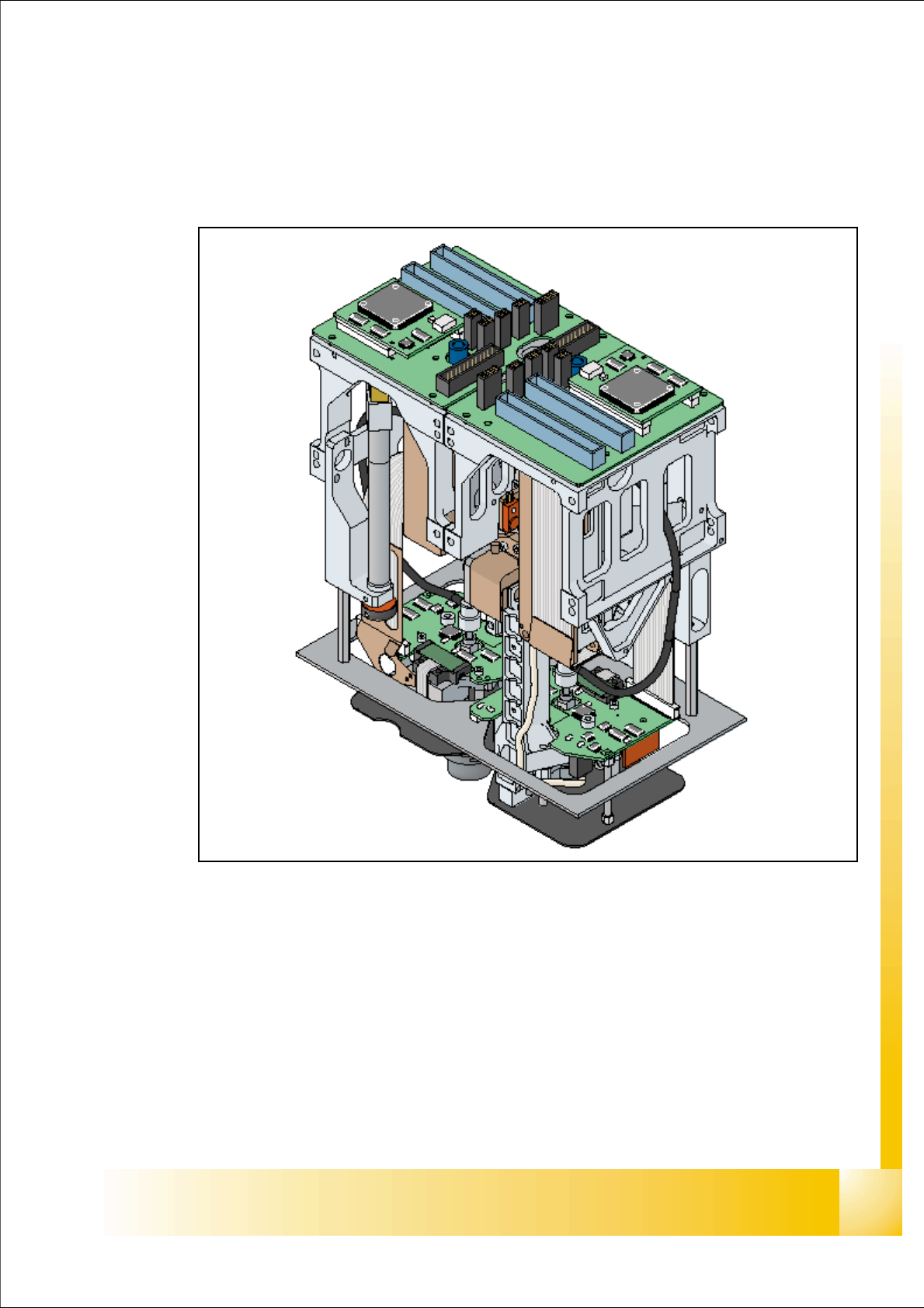
7.3 Pick up and Placement Cycle of the Twin Head
7.3.1 General
Fig. 7.3 - 1 Twin head overview
The module 2 of the TWIN Head is 180 degree mounted to module 1.
The distance between the nozzles is approximately 71 mm in X - direction.
The maximum component height is 25 mm.
Programmable placement force 0.5N – 15N,
Rotational accuracy of 0.07°, 4sigma / X- and Y- axis 35µm 4 sigma.
Improved Odd Shape Component-capabilities (components up to 200x125mm, weight of 100g)
3700 cph for large components
1 - 12
Student Guide SIPLACE HF/HF3
7 TWIN-Head Edition 09/2005
12
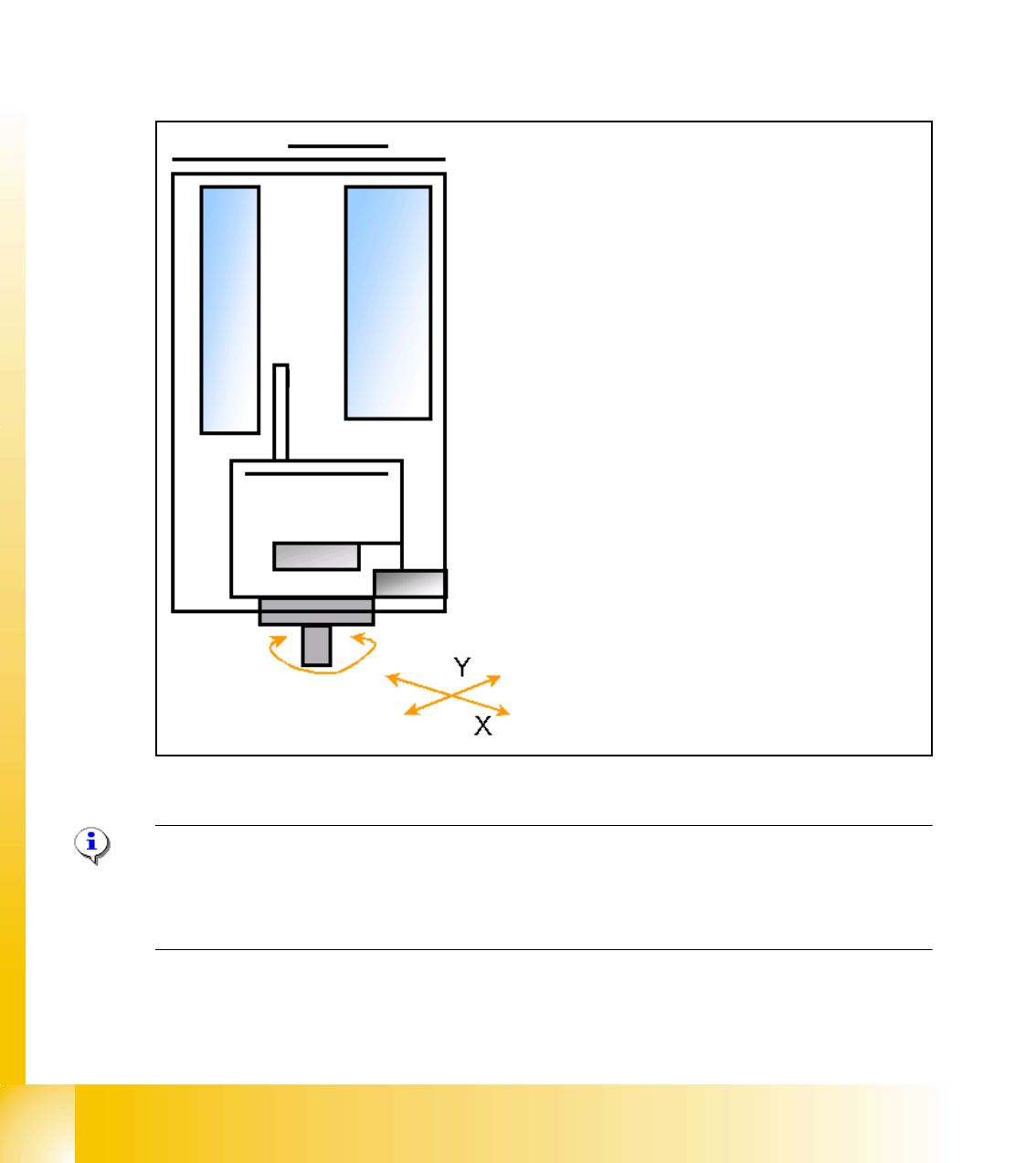
7.3.2 Placement principle Twin-head
During PCB-transport time wait the gantry at theoretical fiducial position to execute PCB-position
recognition (and bad mark recognition) after clamping. With " Whispering down the machine"
gantry 3 (at PA2) center only 2 fiducials of PCB recognition.
Than the TWIN-head start to collect one component with module 1 and one component with mod-
ule 2. Than follows a centering sequence for this two components.
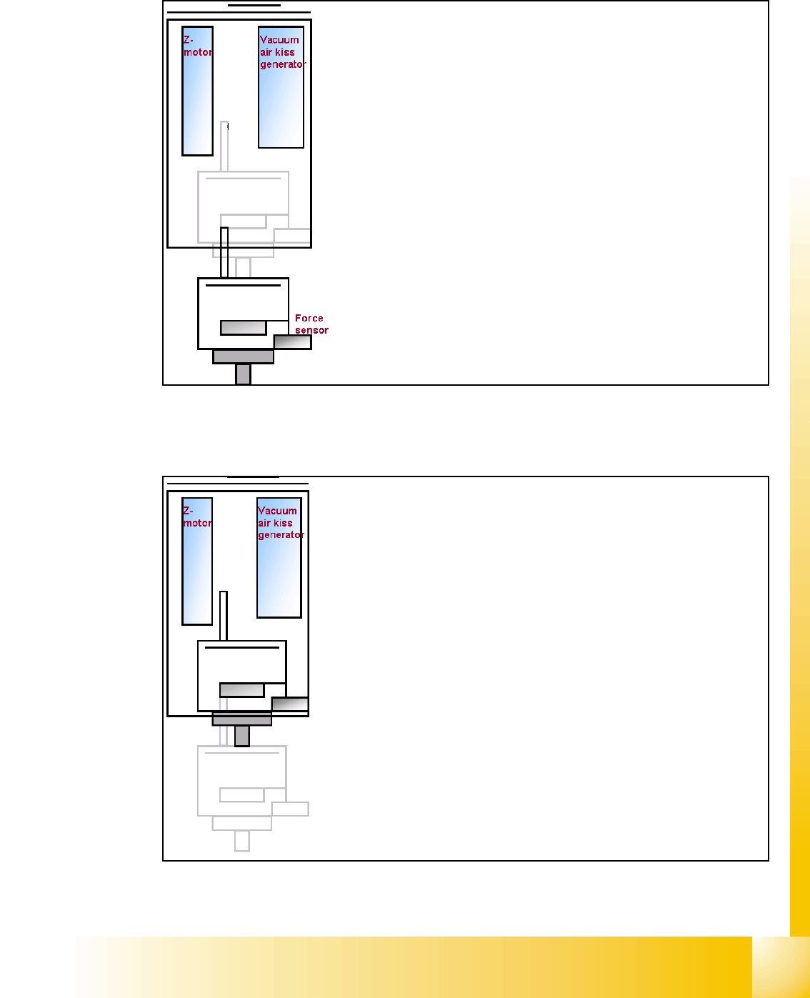
7.3.3 Prepare pick up process module 1
Please Note:
For more accuracy the first five components centered above the IC camera in 0° and 180° at each
PCB board (SW 504). With the SW 505 we will check the offset between nozzle and IC/ FC cam-
era via a fiducial near the IC/FC camera after a defined time of 3 min.
Z-
M
o
t
o
r
D-Motor
– PCB-position recognition and Ink dot recogni-
tion.
– Start X / Y Axis to Pick up position at feeder
track.
– Start D Axis to set the Pick up angle during
X / Y positioning.
– communication to comp. table ‘Feeder ready’
opens component flap.
1 - 13
Student Guide SIPLACE HF/HF3
Edition 09/2005 7 TWIN-Head
13
7.3.3.1 Pick up component module 1
– Z-Axis position downwards with Standard Pick up
mode at 2 N Pick up force.
– At contact with the component the force increase up
to the programmed value.
– At this force level the End signal is triggered and the
Vacuum controlling is activated.
– When Vacuum threshold ‘Pick up’ is measured the Z-
Axis movement upwards start with Standard-position-
ing mode.
– communication to comp. table ‘index Feeder’ when
the Z-Axis reached the "safety height position.
– At end signal Z-Axis top -> Vacuum check ‘comp. on
nozzle’
– Turn with D-Axis the component to the placement an-
gle.
– Prepare pick up with module 2