SG_FSE_SiplaceHF_HF3_00193901-05_eng.pdf - 第33页
1 - 7 S tudent Guide SIPLACE HF/HF3 Edition 09/2005 2 Overview 7 Configuration Siplace HF 2 Fig. 2.1 - 3 Possible configuration Siplace HF Configuration Siplace HF3 2 Fig. 2.1 - 4 Possible configuration Siplace HF3 Compo…

1 - 6
Student Guide SIPLACE HF/HF3
2 Overview Edition 09/2005
6
This data are a basic information on HF-specification. For the actual valid secification data see
’Scope of delivery’ document.
Overview Head Modularity and Benchmark performance HF 3 machine 2
Nozzle distance Twin head 70.8 mm
Maximum component size both nozzle operation 50 x 50 mm (69 x 10 mm)
Maximum component size single nozzle operation 85 x 85 mm (125 x 10 mm)
Placement force 1 - 15 N
Maximum component weigth standard 30 g
Maximum component weigth with restrictions 100 g
Maximum component size stationary camera (single shot) 40 x 50 mm
Resolution stationary camera 79 µ / pixel
Minimum Bump diameter 320 µm
Maximum component size stationary Flip Chip camera (single shot) 8 x 8 mm
Resolution stationary Flip Chip camera 19 µ / pixel
Minimum Bump diameter 80 µm
PCB widths Single conveyor 50 - 508 mm
Maximum PCB lengths Single conveyor (Long Board Option) 50 - 450 mm (610)
Maximum PCB widths Dual conveyor (Single mode operation) 2 x 50 - 250 mm (450mm)
Maximum PCB lengths Dual conveyor (Long Board Option) 50 - 450 mm (610)
PCB thickness 0.3 - 4.5mm
PCB conveyor speed 50 -450 mm/s
Maximum PCB weigth 3 kg
PCB edge clearance 3 mm
PCB changeover time < 2.5 s
Machine size (L x W) 2380 x 2525mm
Heigth of PCB transport 830 - 950mm +/- 15mm
Compressed air pressure 5 - 8 bar
Compressed air consumption RV12/TH or RV6/TH ~ 350 NL/min.
Compressed air consumption RV12/12 ~ 450 NL/min.
Siplace HF3
Placement area 1
Gantry
1 4
Placement area 2
Gantry
2 3
Benchmark per-
formance
( cph )
12 12 - 12
40.400
6 6 - 6
27.600
12 12 - 6
35.700
12 6 - 6
29.600
6 12 - 6
29.600
12 12 - TH
30.100
12 6 - TH
24.000
6 12 - TH
24.000
Placement
head
Configuration
6 6 - TH
22.000
1 - 7
Student Guide SIPLACE HF/HF3
Edition 09/2005 2 Overview
7
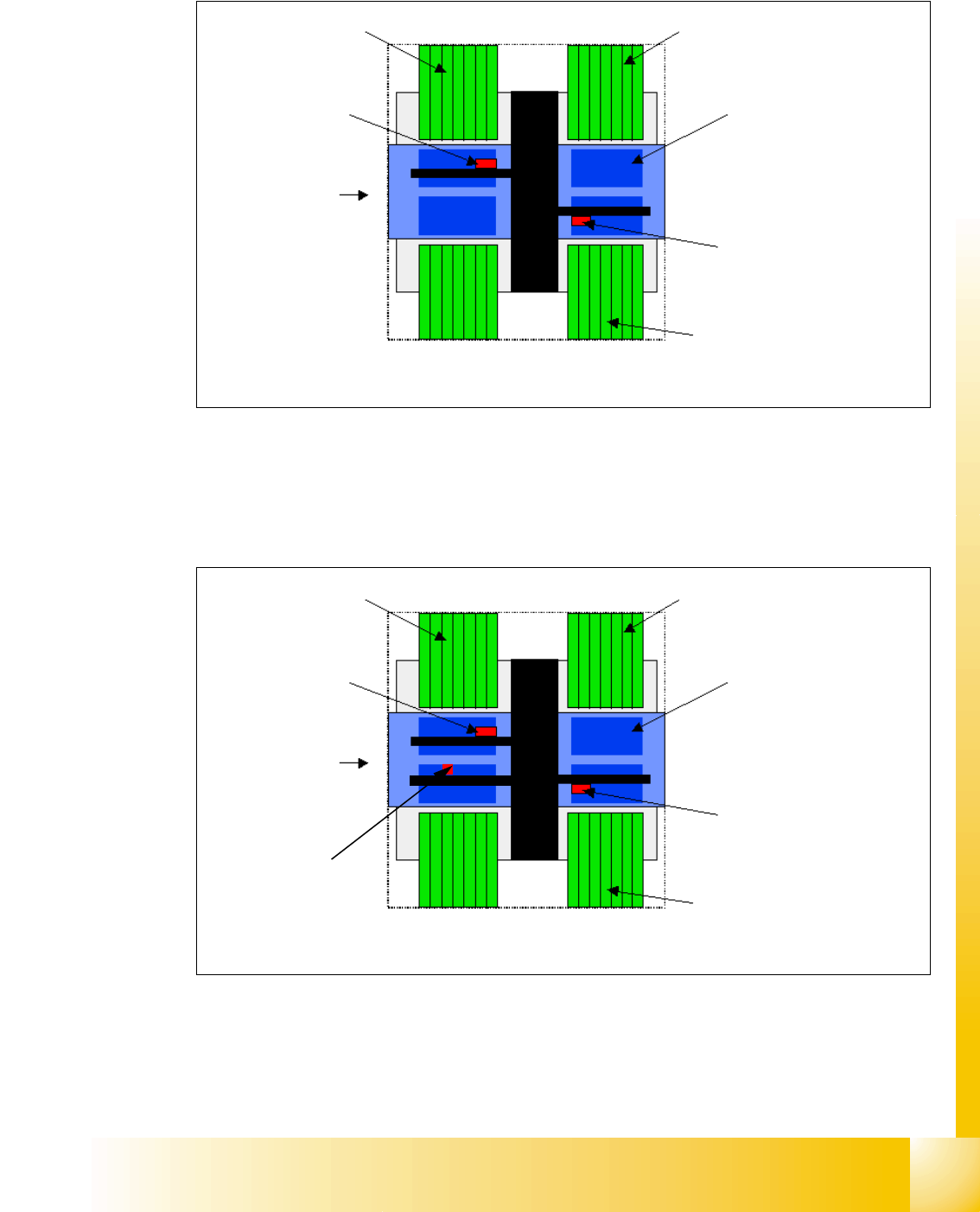
Configuration Siplace HF 2
Fig. 2.1 - 3 Possible configuration Siplace HF
Configuration Siplace HF3 2
Fig. 2.1 - 4 Possible configuration Siplace HF3
Component
table or MTC 2
12 / 6 C&P
head or
Twin head
Transport
direction
15 Slots per table
PCB transport
5 segments
12/6 C&P head or
Twin head
Feeder table or MTC 2
Component
table
12 / 6 C&P
Transport
direction
15 Slots per table
PCB transport
5 segments
12/6 C&P or Twin head
Feeder table or MTC 2
12 / 6 C&P
1 - 8
Student Guide SIPLACE HF/HF3
2 Overview Edition 09/2005
8
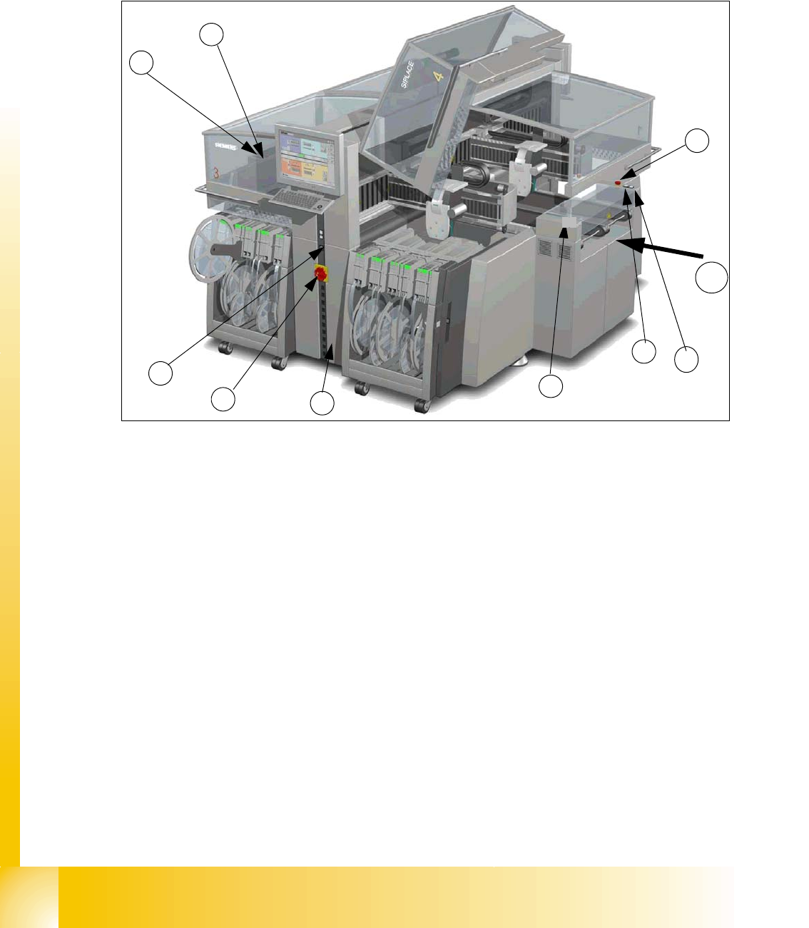
2.2 Overview Units
2.2.1 Switches
Fig. 2.2 - 1 Siplace HF3
(1) Main switch
(2)
Stop button (Black) on the side of Main Power Supply, and pneumatic supply and input side (the first
version had on both sides of the conveyor this button)
(3)
Start button (White) on the side of Main Power Supply, pneumatic supply and input side (the first version
had on both sides of the conveyor this button)
(4) Component Counter on the operater side (Side on the Main Power Supply)
(5) Emergency stop button on the input conveyor side and output conveyor side
(6)
Start button (white) on the output conveyor side (the first version had on both sides of the conveyor
this button)
(7)
Stop button (black) on the output conveyor side (the first version had on both sides of the conveyor
this button)
(8) Service socket inside the power supply unit behind the safety cover
(9) Schmersal safety swtches input- output covers (only at original machine version)
T Transport direction
1
7
9
8
3
5
6
4
T
2