SG_FSE_SiplaceHF_HF3_00193901-05_eng.pdf - 第34页
1 - 8 S tudent Guide SIPLACE HF/HF3 2 Overview Edition 09/2005 8 2.2 Overview Unit s 2.2.1 Switches Fig. 2.2 - 1 Siplace HF3 (1) Main switch (2) Stop button (Black) on the side of Main Power Supply , and pneumatic supply…
1 - 7
Student Guide SIPLACE HF/HF3
Edition 09/2005 2 Overview
7
Configuration Siplace HF 2
Fig. 2.1 - 3 Possible configuration Siplace HF
Configuration Siplace HF3 2
Fig. 2.1 - 4 Possible configuration Siplace HF3
Component
table or MTC 2
12 / 6 C&P
head or
Twin head
Transport
direction
15 Slots per table
PCB transport
5 segments
12/6 C&P head or
Twin head
Feeder table or MTC 2
Component
table
12 / 6 C&P
Transport
direction
15 Slots per table
PCB transport
5 segments
12/6 C&P or Twin head
Feeder table or MTC 2
12 / 6 C&P
1 - 8
Student Guide SIPLACE HF/HF3
2 Overview Edition 09/2005
8
2.2 Overview Units
2.2.1 Switches
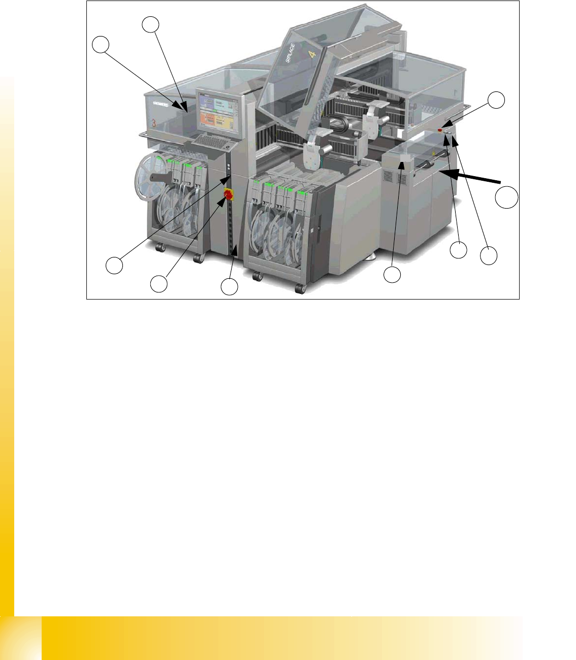
Fig. 2.2 - 1 Siplace HF3
(1) Main switch
(2)
Stop button (Black) on the side of Main Power Supply, and pneumatic supply and input side (the first
version had on both sides of the conveyor this button)
(3)
Start button (White) on the side of Main Power Supply, pneumatic supply and input side (the first version
had on both sides of the conveyor this button)
(4) Component Counter on the operater side (Side on the Main Power Supply)
(5) Emergency stop button on the input conveyor side and output conveyor side
(6)
Start button (white) on the output conveyor side (the first version had on both sides of the conveyor
this button)
(7)
Stop button (black) on the output conveyor side (the first version had on both sides of the conveyor
this button)
(8) Service socket inside the power supply unit behind the safety cover
(9) Schmersal safety swtches input- output covers (only at original machine version)
T Transport direction
1
7
9
8
3
5
6
4
T
2
1 - 9
Student Guide SIPLACE HF/HF3
Edition 09/2005 2 Overview
9
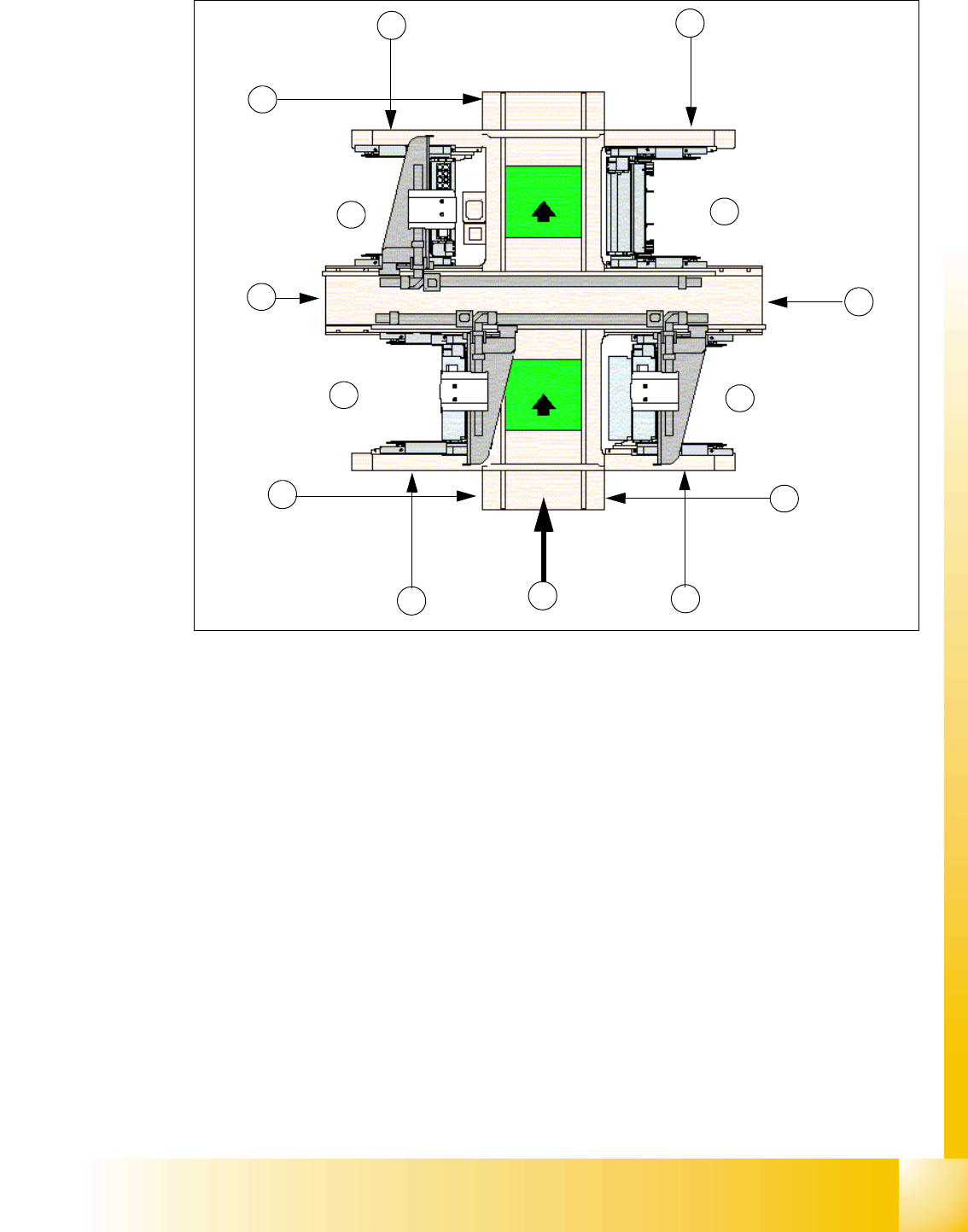
Fig. 2.2 - 2 Siplace HF3
Legend
(1) Sector 1 (2) Sector 2 (Main Distributor)
(3) Sector 3 (4) Sector 4 (Sub Distributer)
(5) Transport direction (6) Pneumatic unit & Control unit conveyor
(7) Component changeover table (8) Computer unit
(9) Position for Component changeover table
or MTC 2 for BB 2
(10) Position for Component changeover table
or MTC 2 for BB 1 (MTC only HF)
(11) Axis unit in PA 1 for HF3 (12) Axis unit in PA 2
(13) Power supply unit
1
2
8
3
5
6
4
7
7
9
10
11
PA 1
PA 2
13
12