SG_FSE_SiplaceHF_HF3_00193901-05_eng.pdf - 第372页
1 - 4 S tudent Guide SIPLACE HF/HF3 8 Component handling Edition 09/2005 4 8.1.2 Pneumatic t ape cutter and empty t ape duct The pneumatic t ape cutter unit is fixed to the frame of the do cking unit with 4 screws. It cu…
1 - 3
Student Guide SIPLACE HF/HF3
Edition 09/2005 8 Component handling
3
COT model for ’A’-machine with One -Hand Operation 8
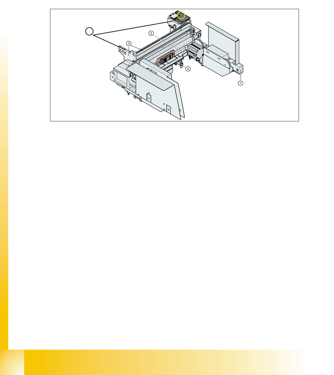
The docking unit is identical for both v ersions of the COT! the electrical circuit is changed for one
hand operation.
For the docking process, push the component changeover table into the docking unit as much as
possible, the safety cover have to be be closed. Press button (3) (see Fig. 10.1 - 1) and the COT
is mounted to the machine like described before.
For the undocking process, open the safety cover at the respective area and press button 3 (see
Fig. 10.1 - 1). Now the COT move out like described before.
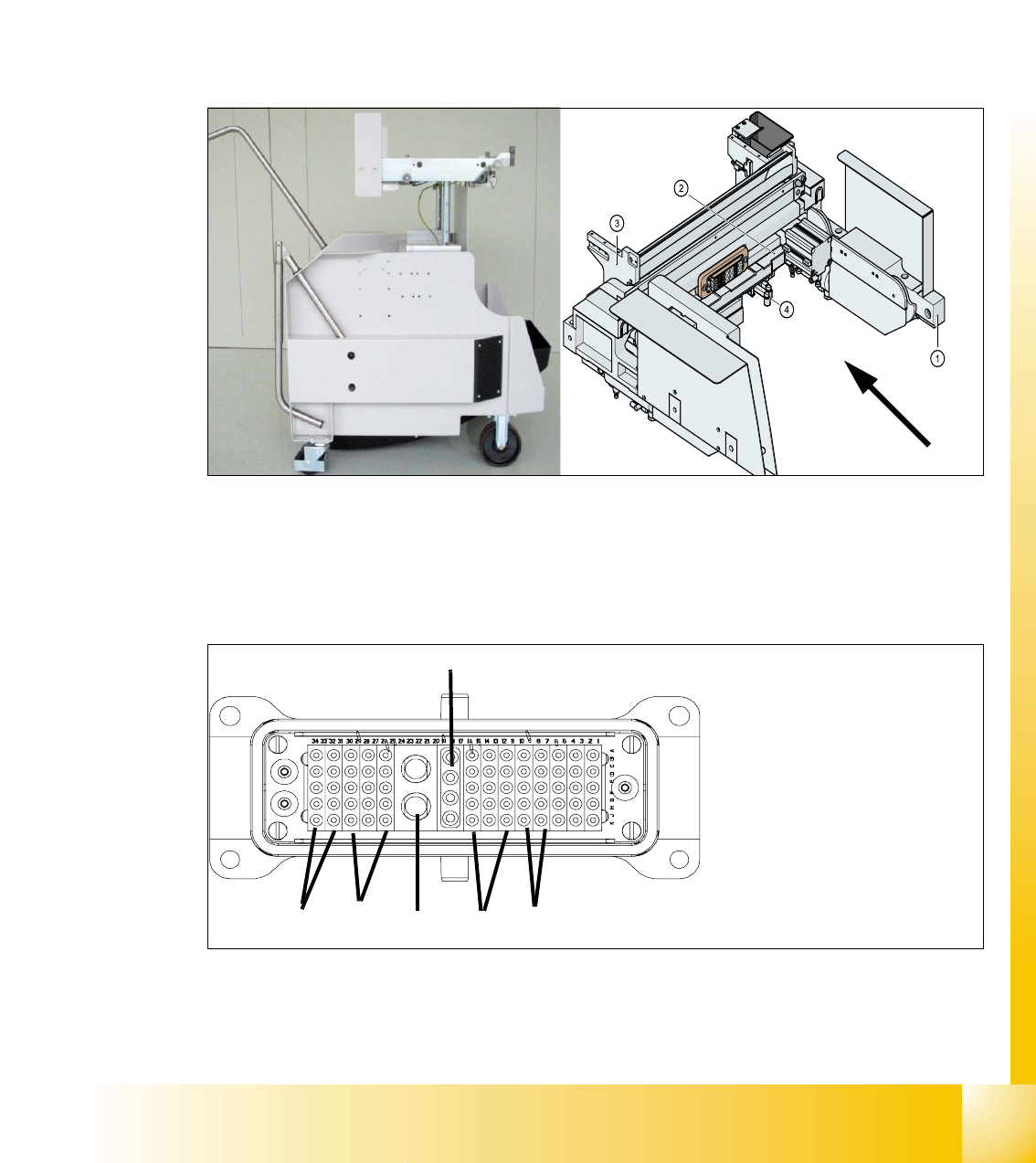
Fig. 8.1 - 3 COT -model 2 with the docking unit
Connection the COT to the machine 8
Fig. 8.1 - 4 ODU Connector for COT (first model)
1. Power
2. Safety loop
3. Signaling
4. Compressed air Bulk Case
5. Splice detection
6. CAN Bus
(4)
(5)
(2)
(1)
(3)
(6)
1 - 4
Student Guide SIPLACE HF/HF3
8 Component handling Edition 09/2005
4
8.1.2 Pneumatic tape cutter and empty tape duct
The pneumatic tape cutter unit is fixed to the frame of the docking unit with 4 screws. It cuts plastic,
aluminum and paper tapes up to a maximum pocket depth of 25 mm. The waste tape fall via the
tape waste chute into the tape waste container below the component table. The empty tape duct
is constructed, that the cutting edges of the tape cutter is covered (Safety), the empty tape duct
has an integrated reject box and mounting suface for nozzle changers of 6 or12 nozzle C&P head
or Twin head.
Fig. 8.1 - 5 Complete docking unit
1. Frame docking unit 2. Pneumatic tape cutter
3. Empty tape duct 4. Electrically and pneumatically connector to the machine
5. Support for the nozzle changer (6) Component reject box for C&P-head
5
6
1 - 5
Student Guide SIPLACE HF/HF3
Edition 09/2005 8 Component handling
5
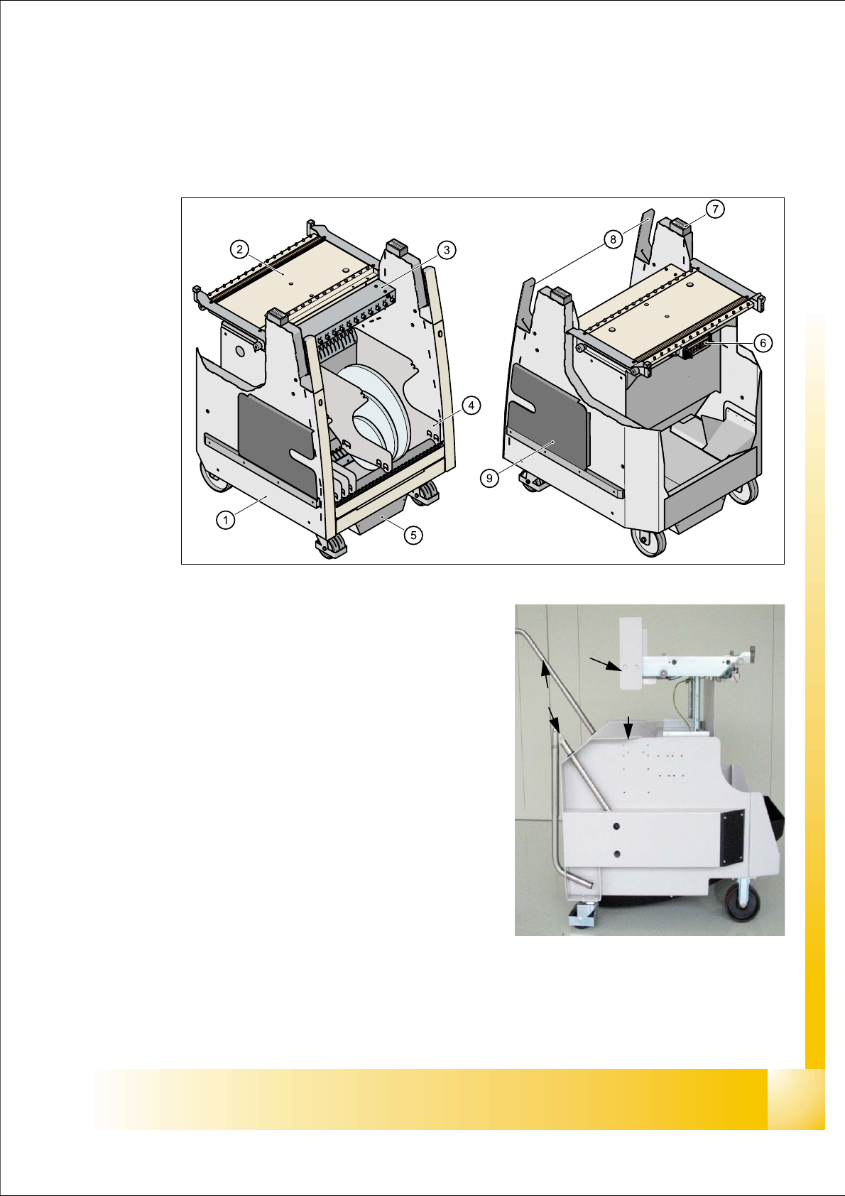
8.2 Component changeover table
8.2.1 Structure of the component table
Fig. 8.2 - 1 Component changeover table front view and rear view
(1) Moveable base
(2) Feeder table plate
3. Communication unit; splice detection unit is ad-
ditional mounted below the communication unit
LED-Display Communication unit:
RED (Left) - Reset Communication unit
GREEN (Center) - Display Power supply --> OK
Yellow (Right) - Logic OK ( from Version-03:
Standard OFF, it flashes in the case
of the download of the unit)
(4) Tape reels container
(5) Tape waste container
(6) Interface power supply, communication, safety
loop
(7) Sticker with an Identification number as alphanu-
meric Signs and as an barcode
(8) Handles (for model 2 seperate to swifel)
(9) Slot for set up lists on both sides
(1)
(8)
(3)
(4)
(5)
(5)
(2)
(6)