SG_FSE_SiplaceHF_HF3_00193901-05_eng.pdf - 第374页
1 - 6 S tudent Guide SIPLACE HF/HF3 8 Component handling Edition 09/2005 6 8.2.2 Function description of th e component changeover t able 8.2.2.1 Docking The docking process can on ly be perform w hen the machine is powe…
1 - 5
Student Guide SIPLACE HF/HF3
Edition 09/2005 8 Component handling
5
8.2 Component changeover table
8.2.1 Structure of the component table
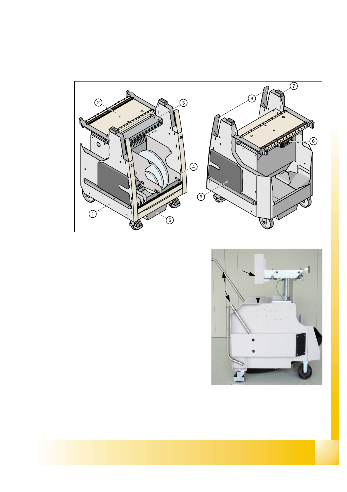
Fig. 8.2 - 1 Component changeover table front view and rear view
(1) Moveable base
(2) Feeder table plate
3. Communication unit; splice detection unit is ad-
ditional mounted below the communication unit
LED-Display Communication unit:
RED (Left) - Reset Communication unit
GREEN (Center) - Display Power supply --> OK
Yellow (Right) - Logic OK ( from Version-03:
Standard OFF, it flashes in the case
of the download of the unit)
(4) Tape reels container
(5) Tape waste container
(6) Interface power supply, communication, safety
loop
(7) Sticker with an Identification number as alphanu-
meric Signs and as an barcode
(8) Handles (for model 2 seperate to swifel)
(9) Slot for set up lists on both sides
(1)
(8)
(3)
(4)
(5)
(5)
(2)
(6)
1 - 6
Student Guide SIPLACE HF/HF3
8 Component handling Edition 09/2005
6
8.2.2 Function description of the component changeover table
8.2.2.1 Docking
The docking process can only be perform when the machine is power on , compressed air is sup-
plied to the machine and the safety cover have to be closed.
For docking the COT move the table into the machine as far as possible, keep safety cover closed
and press the button (One hand operation). On the left and right from the empty tape duct are two
centering pins to center the COT for the final correct pick up position.
At docking procedure the component table plate raise (depend on machine and COT height) and
is pulled into the machine automatically. Two pneumatic cylinders with cam disks on the left and
right side of the COT move the trolley.
8.2.2.2 Undocking
When machine is running:
For undocking the COT open the safety cover and press the but-
ton 1. The component table is pushed out with two additional pneumatic cylinders at the left and
right of the empty tape duct. The COT is lowered by the cam disks. The COT electrical and pneu-
matic supply will be automatically disconnected from the machine.
When machine is OFF: Remove the COT for service without electrical and pneumatic power
supply -> Open the safety cover an pull out the COT on the handles.
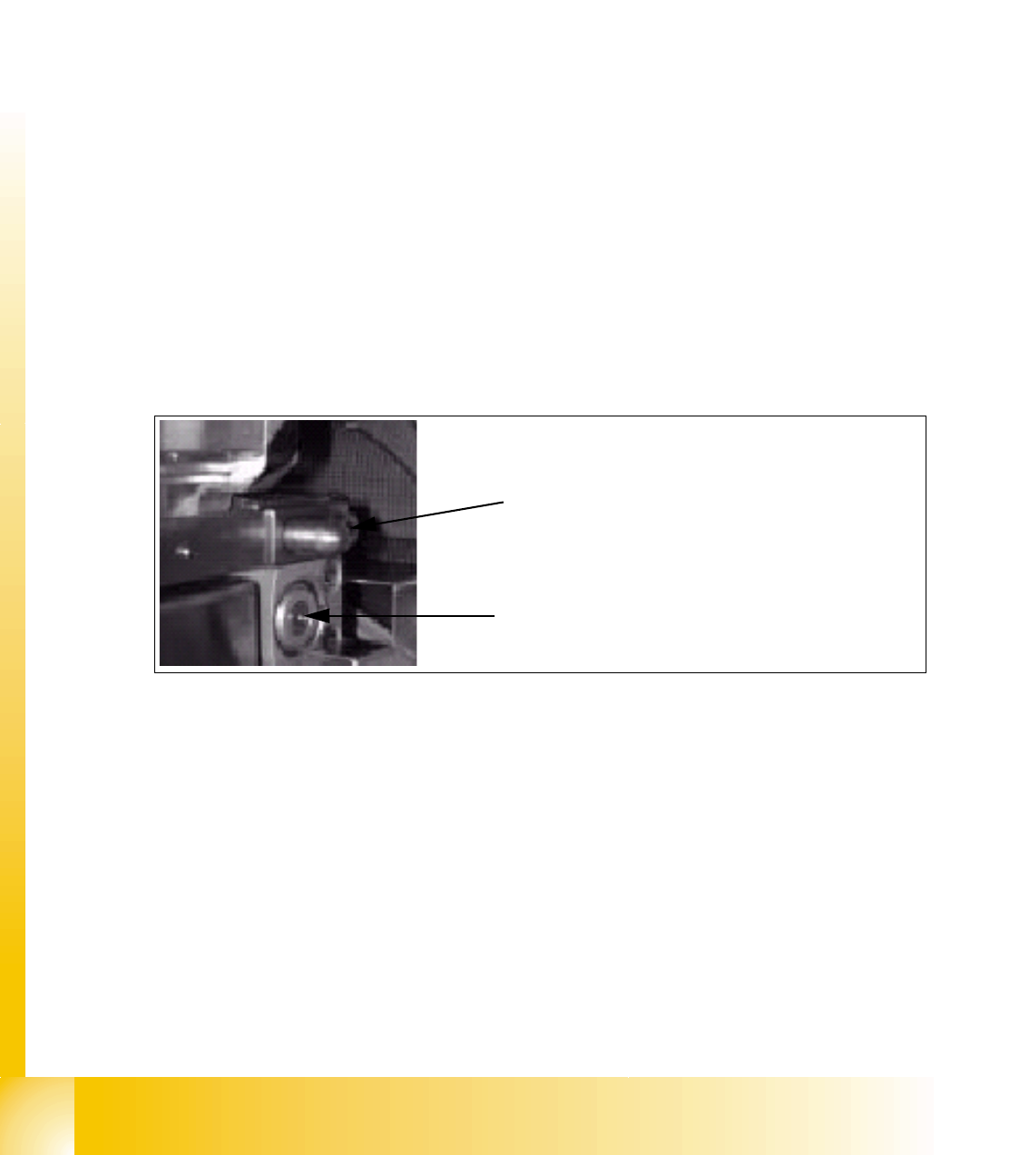
Fig. 8.2 - 2 Centering pin and pneumatic cylinder at the left and right of COT
Centering Pin for the table plate
Cylinder pushing out the COT at undocking
1 - 7
Student Guide SIPLACE HF/HF3
Edition 09/2005 8 Component handling
7
8.2.2.3 Adjustment pneumatic cylinder
The movement of the CAM-disks at the docking unit, left and right side can be individually adjus-
ted at the round cylinder
Note:
If you adjust the pneumatics cylinder is to be ensured that the COT is moved in parallel into the
docking unit. The docking and undocking procces of the COT should be set to
approx. 2 seconds.
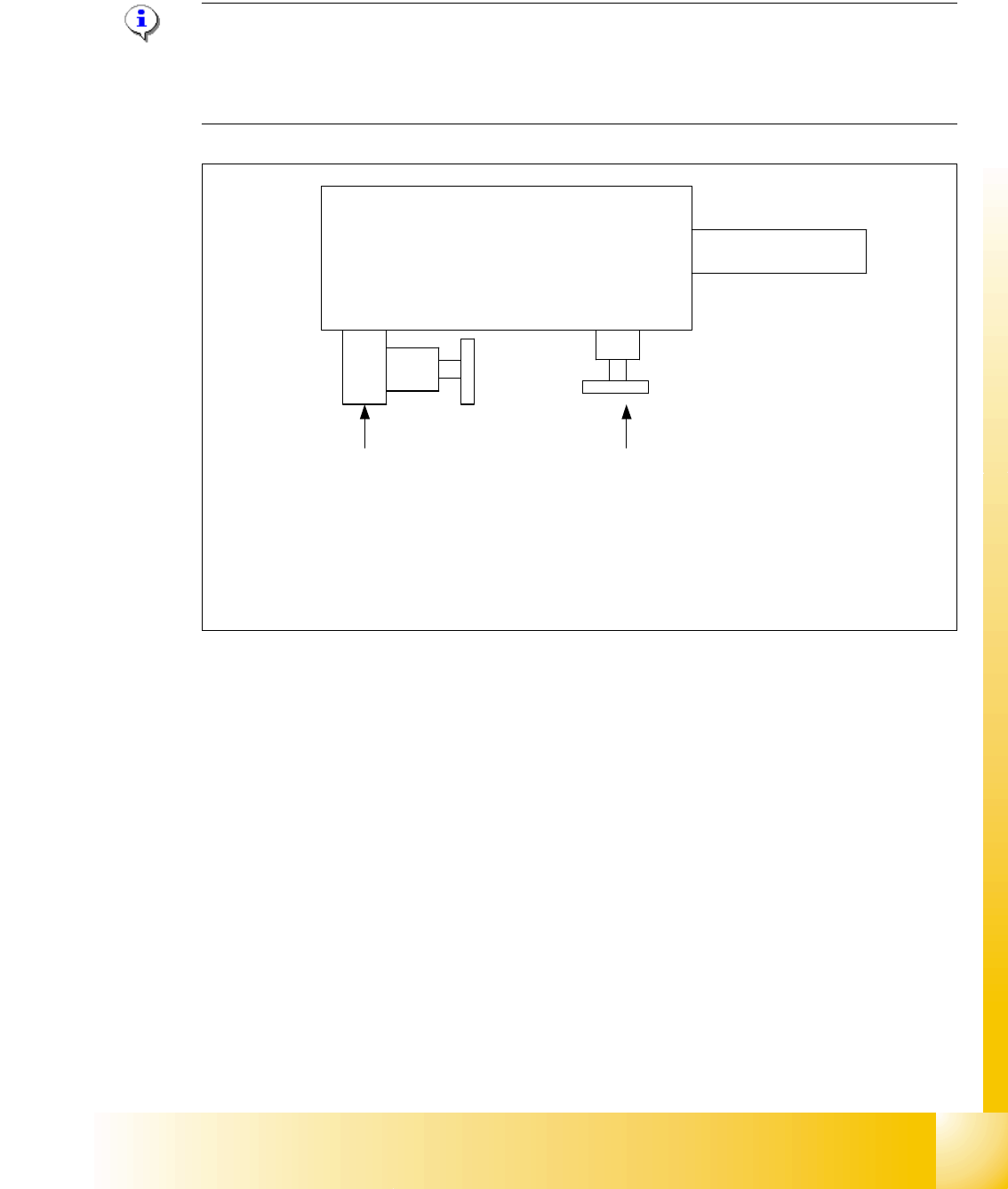
Fig. 8.2 - 3 Adjustment the pneumatic cylinder on the docking unit
Valve setting
Time characteristic for
docking the COT
Valve setting
Time characteristic for
undocking the COT
Pneumatic cylinder
Docking unit
Piston rod
Setting valve anticlockwise: Increase the time for the docking and undocking process
Setting valve clockwise: Reduce the time for the docking and undocking process