SG_FSE_SiplaceHF_HF3_00193901-05_eng.pdf - 第380页
1 - 12 S tudent Guide SIPLACE HF/HF3 8 Component handling Edition 09/2005 12 8.2.4.3 Additional feeder fixation The Feeder-Fixing is an additional mechanical safety precau tion. It prevent to move the fe eder at the comp…
1 - 11
Student Guide SIPLACE HF/HF3
Edition 09/2005 8 Component handling
11
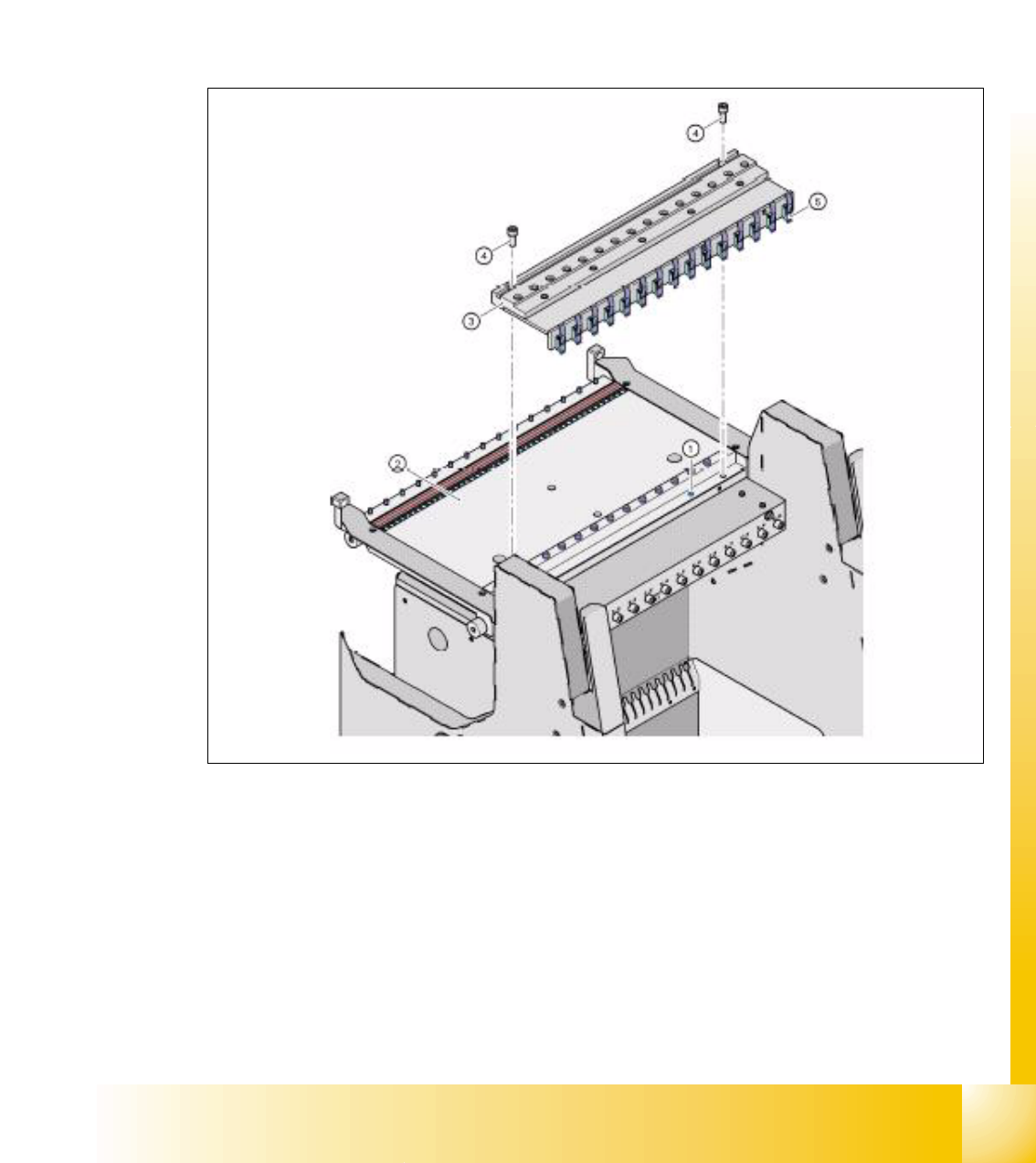
8.2.4.2 Compressed air supply for Bulkcase feeder
Bulkcase feeder need for operation pressure air supply. So this pressure air supply is offered as
an option .
it is easy to mount. First remove the bung (Pos. 1) at pressure air hose in the feeder table (Pos.
2). Than the pneumatic supply for the bulck case feeder is mounted (Pos. 3) with 2 screws DIN
912, M8x20 (Pos. 4) on the component table (Pos. 2). At the rear side of the airkiss supply unit
are feeder clamps mounted (Pos. 5). This clamps keep the Bulkcase-feeder down correctly sealed
to the pressure air supply.
Fig. 8.2 - 8 Unit for bulkcase feeder
Legend
(1)Bung at component table 2. Componnent table
3. Pressure air supply for Bulkcase-Feeder 4. Screw DIN 912, M8x20
5. clamps for bulkcase feeder
1 - 12
Student Guide SIPLACE HF/HF3
8 Component handling Edition 09/2005
12
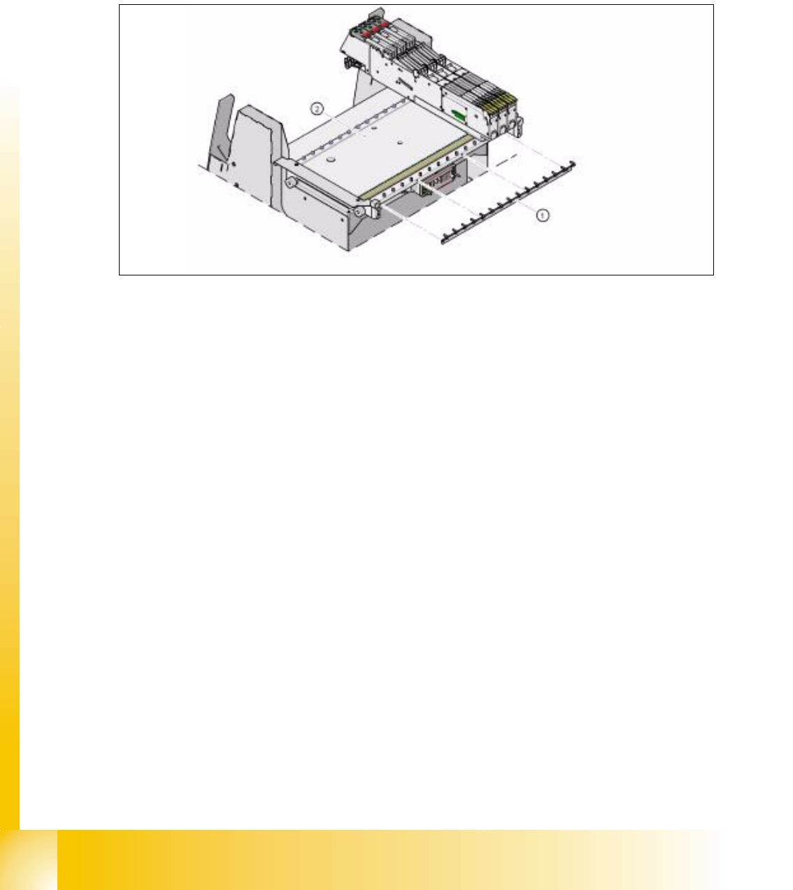
8.2.4.3 Additional feeder fixation
The Feeder-Fixing is an additional mechanical safety precaution. It prevent to move the feeder at
the component table by accident. It exclude a head crash risk with a wrong positioned feeder.
The feeder-fixation is is mounted on the front side of the component table. The clamp lock the front
feeder stand. Forthe full set up of this option each feeder table get such a clamp.
Fig. 8.2 - 9 COT feeder fixation
Legend
(1)Feeder fixation 2. Component table
1 - 13
Student Guide SIPLACE HF/HF3
Edition 09/2005 8 Component handling
13
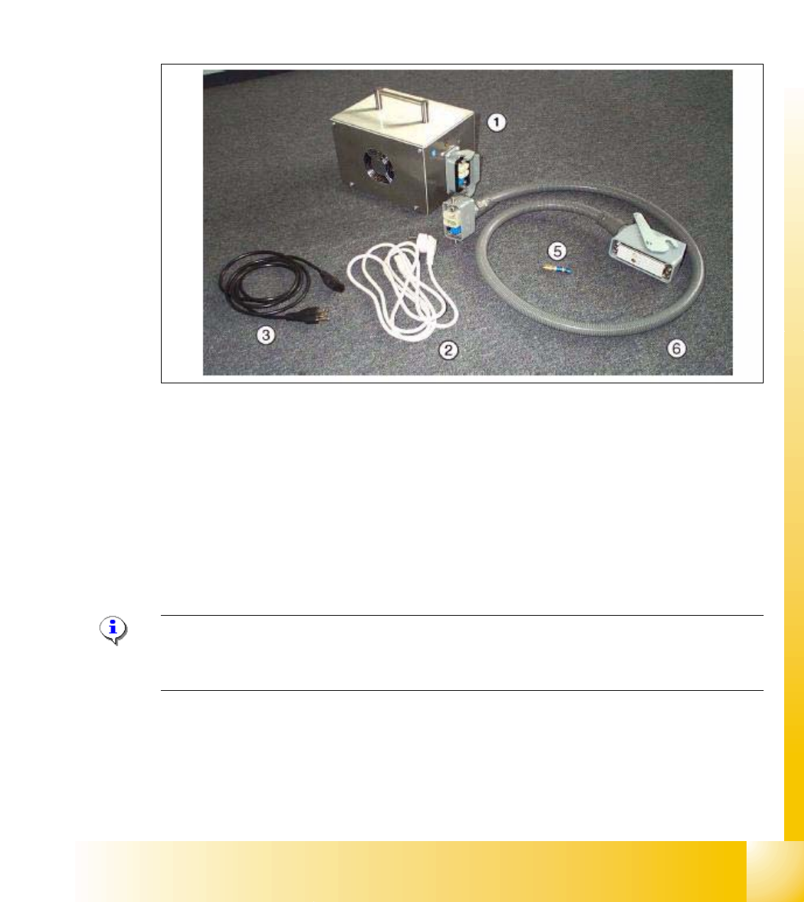
8.2.4.4 External Power supply for Siplace component table
To decresse the set up time of the machine the component tables could be externally set up with
the new feeder set up. All the feeder settings and functions could be checked externally. With a
external power supply the feeder table is supplied with power and pressure air supply.
Technical Data:
Netzspannung 230 V~ ± 5 % / 120 V~ ± 5 %
Druckluftanschluss max. 1,0 MPa (10 bar) Ausgangsdruck mit Ventil regelbar
Fig. 8.2 - 10 parts of the external power supply
Legend
7
Note:
For more Information, please order the "External power supply component trolley" document
(Item no.: 00193903-01)
(1)Power supply for 88...264 V AC (2)
Power supply cable 230 V AC (EU 3x0.75
mm
2, l = 2.0 m)
(3) Power supply cable 125 V AC (US 3x18
AWG, l =2.0 m)
(5) Pneumatic coupling
(6) Cable to power the component trolley