SG_FSE_SiplaceHF_HF3_00193901-05_eng.pdf - 第381页
1 - 13 S tudent Guide SIPLACE HF/HF3 Edition 09/2005 8 Component handling 13 8.2.4.4 External Power supply for Siplace component t able T o decresse the set up time of the machine the component t ables could be externall…
1 - 12
Student Guide SIPLACE HF/HF3
8 Component handling Edition 09/2005
12
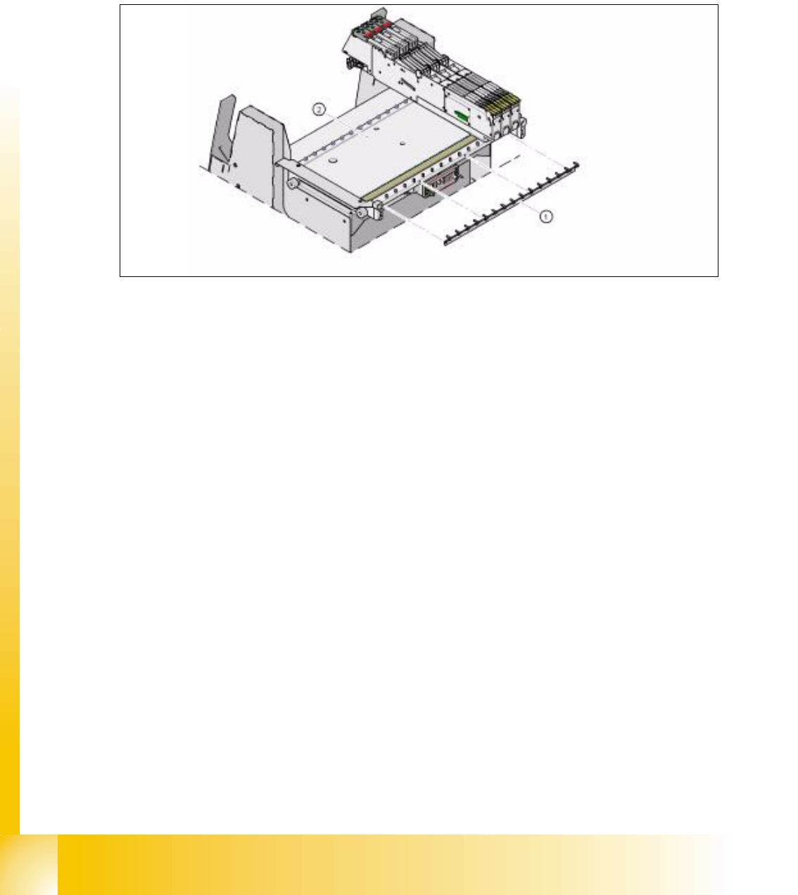
8.2.4.3 Additional feeder fixation
The Feeder-Fixing is an additional mechanical safety precaution. It prevent to move the feeder at
the component table by accident. It exclude a head crash risk with a wrong positioned feeder.
The feeder-fixation is is mounted on the front side of the component table. The clamp lock the front
feeder stand. Forthe full set up of this option each feeder table get such a clamp.
Fig. 8.2 - 9 COT feeder fixation
Legend
(1)Feeder fixation 2. Component table
1 - 13
Student Guide SIPLACE HF/HF3
Edition 09/2005 8 Component handling
13
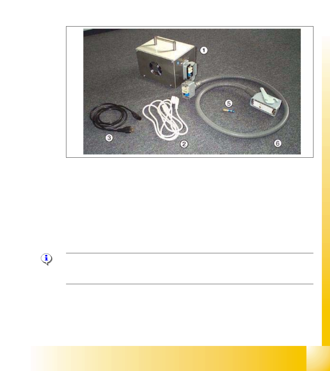
8.2.4.4 External Power supply for Siplace component table
To decresse the set up time of the machine the component tables could be externally set up with
the new feeder set up. All the feeder settings and functions could be checked externally. With a
external power supply the feeder table is supplied with power and pressure air supply.
Technical Data:
Netzspannung 230 V~ ± 5 % / 120 V~ ± 5 %
Druckluftanschluss max. 1,0 MPa (10 bar) Ausgangsdruck mit Ventil regelbar
Fig. 8.2 - 10 parts of the external power supply
Legend
7
Note:
For more Information, please order the "External power supply component trolley" document
(Item no.: 00193903-01)
(1)Power supply for 88...264 V AC (2)
Power supply cable 230 V AC (EU 3x0.75
mm
2, l = 2.0 m)
(3) Power supply cable 125 V AC (US 3x18
AWG, l =2.0 m)
(5) Pneumatic coupling
(6) Cable to power the component trolley
1 - 14
Student Guide SIPLACE HF/HF3
8 Component handling Edition 09/2005
14
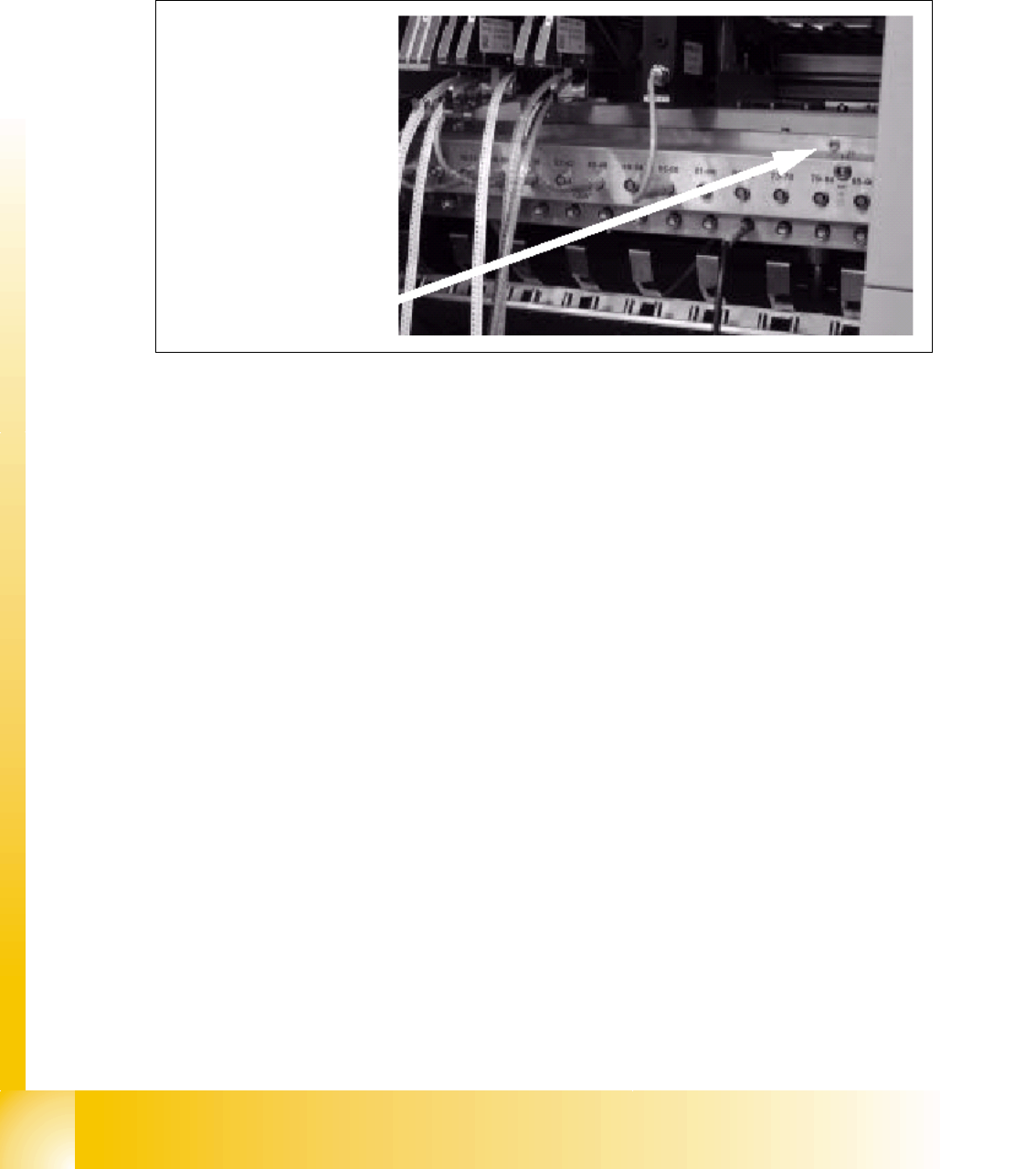
8.2.4.5 Additional Communication unit for splice detection
An additional communication unit for the option Traceability with splice detection is necessary.
Splice detector is connected to this communication unit. The communication unit sent an informa-
tion to the SC software when a splice is detected at the component tape.This set the new fill level
for this component automatically.
Fig. 8.2 - 11 Additionally communication unit for splice detection
(1) The additionally communication unit is mounted together with the communication unit on the
component changeover table.
1