SG_FSE_SiplaceHF_HF3_00193901-05_eng.pdf - 第383页
1 - 15 S tudent Guide SIPLACE HF/HF3 Edition 09/2005 8 Component handling 15 8.3 Pneumatic t ape cutter 8.3.1 Structure and function of the pneumatic t ape cutter The ta pes guided into th e slot (3) of the t ape cutter …
1 - 14
Student Guide SIPLACE HF/HF3
8 Component handling Edition 09/2005
14
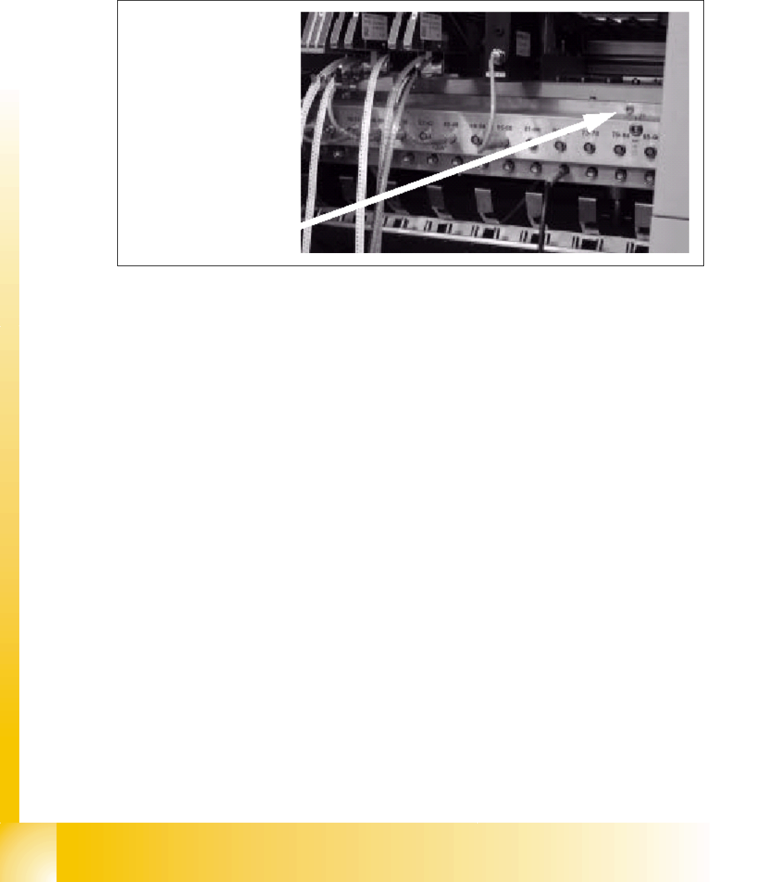
8.2.4.5 Additional Communication unit for splice detection
An additional communication unit for the option Traceability with splice detection is necessary.
Splice detector is connected to this communication unit. The communication unit sent an informa-
tion to the SC software when a splice is detected at the component tape.This set the new fill level
for this component automatically.
Fig. 8.2 - 11 Additionally communication unit for splice detection
(1) The additionally communication unit is mounted together with the communication unit on the
component changeover table.
1
1 - 15
Student Guide SIPLACE HF/HF3
Edition 09/2005 8 Component handling
15
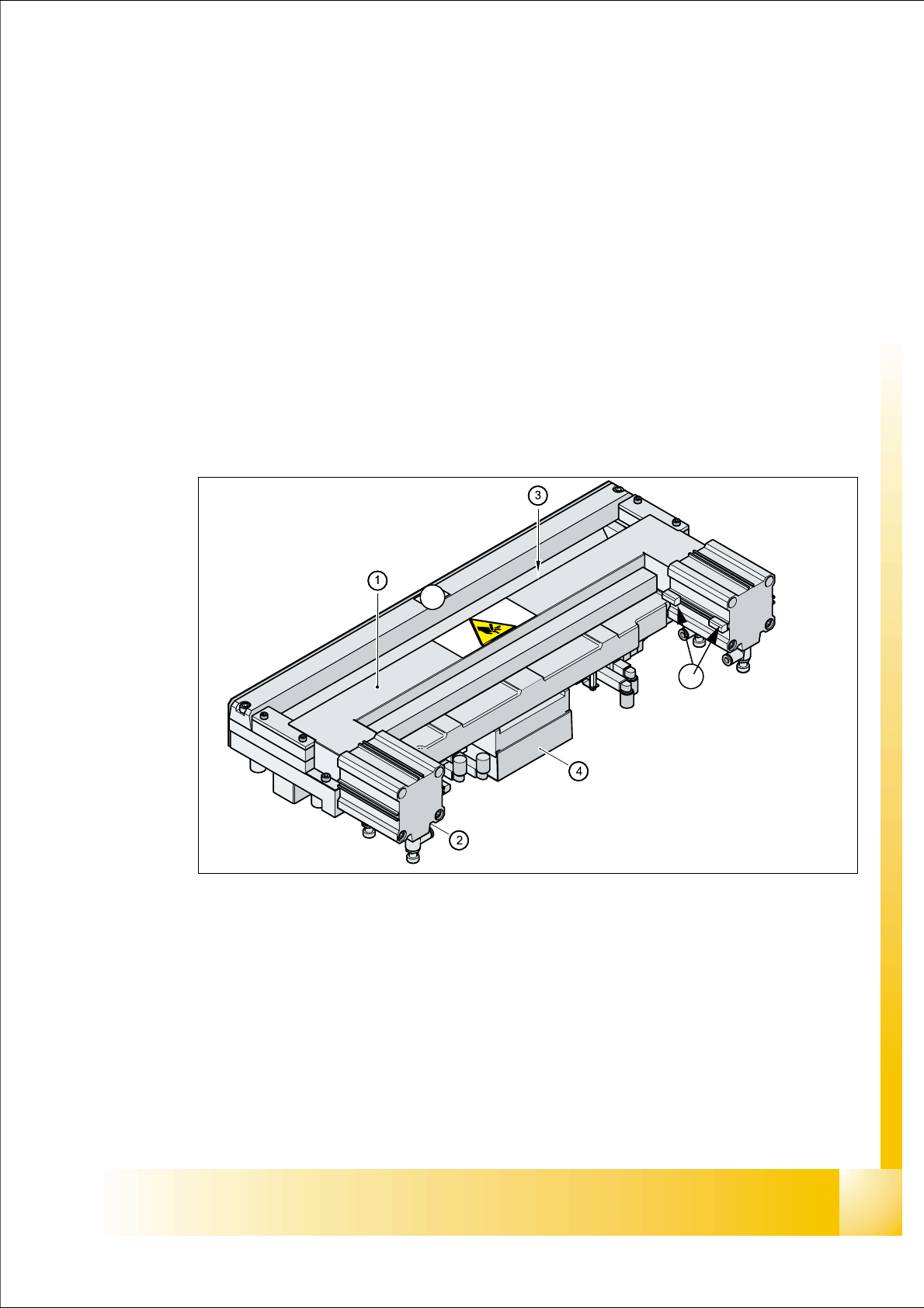
8.3 Pneumatic tape cutter
8.3.1 Structure and function of the pneumatic tape cutter
The tapes guided into the slot (3) of the tape cutter via the empty tape duct (Pos.3 in Fig. 8.3 - 1).
The tape cutter is based on a horizontal frame (Pos.1) with a fixed cutting blade(6) and a moving
cutting blade that is driven by two pneumatic cylinders (Pos. 2). With every in and out movement,
the device cuts off the tape.
Proximity switches (Pos. 5) signal the position of the pneumatic cylinder pistons, and thus the
cutting blade. The electronic control unit (4) thus registers, for example, that a component that
remained in the tape was not cut. Cutting only takes place during placement. For operational
safety reasons, the tape cutter is integrated into the emergency stop circuit.
The pneumatic tape cutter is fixed on the frame of the docking unit with four screws and this, to-
gether with the empty tape duct is a complete unit.
Fig. 8.3 - 1 Pneumatic tape cutter
The Tape cutter is activated when the gantry is moving to the placement position. Alternating one
of the cylinders start to front position. The signal ’in front’ from the first cylinder start the cylinder
on the other side. Both signals ’blade in front position’ trigger control unit to withdraw both cylin-
ders at the same time.
(1)Horizontal frame 2. Pneumatic cylinder
3. Slot for empty tape 4. Electronic control unit
5. Proximity switch 6. fixed cutter blade
5
6
1 - 16
Student Guide SIPLACE HF/HF3
8 Component handling Edition 09/2005
16
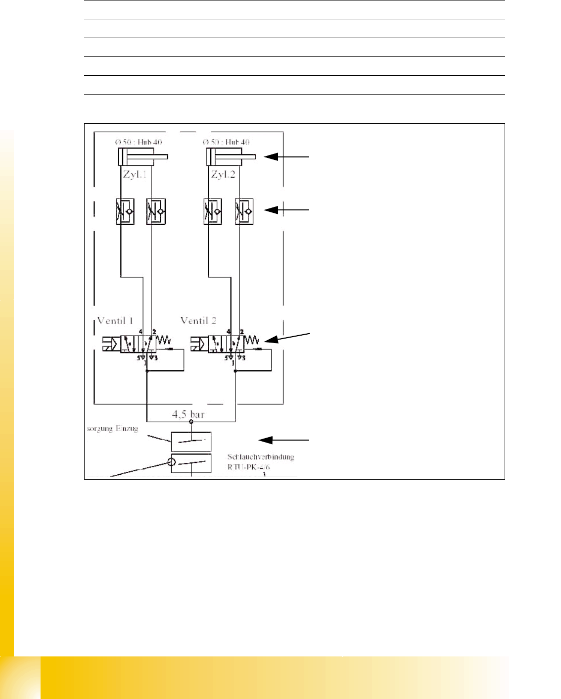
Technical data 8
Fig. 8.3 - 2 Pneumatic scheme Tape cutter
Compressed air supply 0.5 MPa = 5.0 bar
Safety enabled with a solenoid when the machine safety loop is closed
Compressed air consumption 135 l/min.
Cycle time 1.5 sec per cut
Supply voltages 5 VDC, 24 VDC
Pneumatic cylinder for the cutting blade
movement 40 mm
Adjustable throttle valve on the pneumatic
cylinder
5/2 way magnetic valve
4,5 Bar compressed air supply integrated
into the safety loop. Tape cutter is active
with closed safety covers only