SG_FSE_SiplaceHF_HF3_00193901-05_eng.pdf - 第39页
1 - 13 S tudent Guide SIPLACE HF/HF3 Edition 09/2005 2 Overview 13 2.2.3 Pneumatic unit The pneumatic unit is mounted on a compact slide- in module, and located on the right side of the middle section. A lockable door pr…

1 - 12
Student Guide SIPLACE HF/HF3
2 Overview Edition 09/2005
12
K5 contactor A1 (+) – A2
(-)
1,2
3,4
5,6
24VDC
24 VDC
against ground
24 VDC against ground
24 VDC against ground
K6 (SSK)
protective contactor
combination
L+, X3, X5 24 VDC against ground
F1 Fuse Service socket;
1-pol.
1, 2 115 VAC / 220 VAC
230 VAC / 240 VAC
F2 Fuse Component table;
3-pol.
1, 3, 5 u.
2, 4, 6
3 x 36 VAC
F4 Fuse X- / Y-Axis;
3-pol.
1, 3, 5 u.
2, 4, 6
3 x 177 VAC
F5 Fuse Star-Axis;
1-pol.
1, 2 145 VDC
against ground
F6 Fuse Z- and DP-Axis;
1-pol.
1, 2 39 VDC against ground
F7 Fuse supply system on
bord;
3-pol.
1, 3, 5 u.
2, 4, 6
3 x 230 VAC
F8 Fuse PCB Conveyor;
1-pol.
1, 2 33 VDC
against ground
F10 Fuse rectifier V7 and V70;
3-pol.
1, 3, 5 u.
2, 4, 6
3 x 39 VAC
F11 Fuse inrush limiter; 1-pol. 1, 2 33,6 VDC
against ground
F12 Fuse illumination
1-pol.
1, 2 52 VDC against ground
F13 Fuse Monitor;
1-pol.
1, 2 26 VDC against ground
F14 Fuse Blower Y-Motor;
1-pol.
1, 2 26 VDC against ground
F61 / F62 Fuse rectifier V4 3 x 28 VAC
F81 / F82 Fuse rectifier V5 3 x 23,8 VAC
F111 / F112 Fuse rectifier V8 3 x 23,8 VAC
F131 / F132 Fuse rectifier V10 3 x 19,7 VAC
F141 / F142 Fuse rectifier V11 3 x 18,7 VAC
1 - 13
Student Guide SIPLACE HF/HF3
Edition 09/2005 2 Overview
13
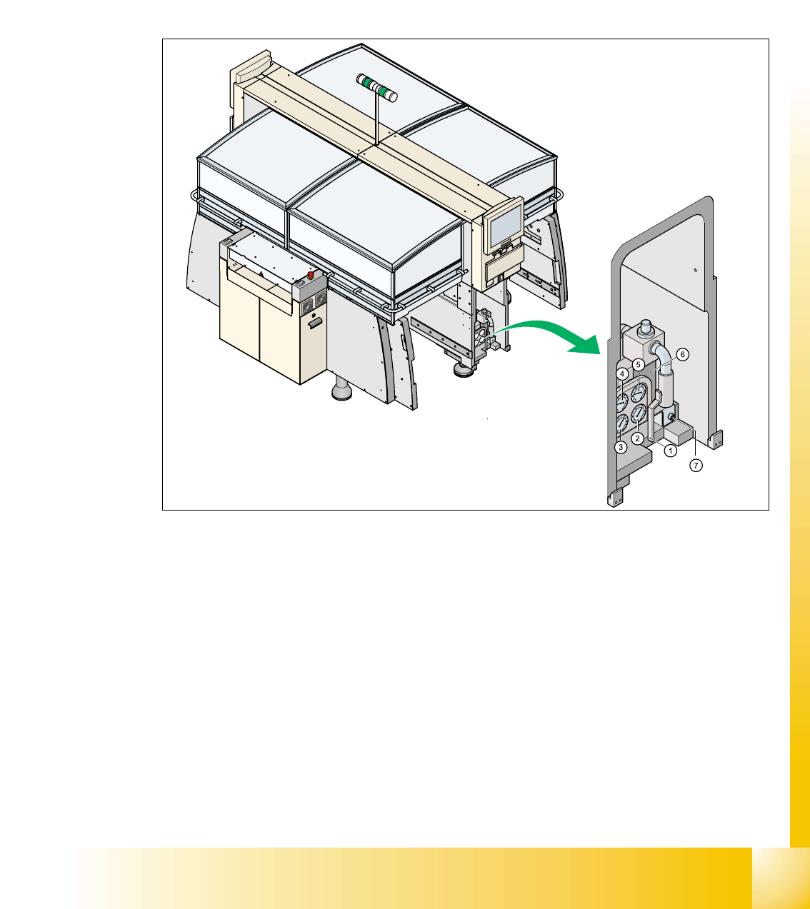
2.2.3 Pneumatic unit
The pneumatic unit is mounted on a compact slide-in module, and located on the right side of the
middle section. A lockable door prevents access to the unit.
Open you the cover of the pneumatic unit with machine key. In the pneumatic unit contain the
whole sensors and valves of the compressed air supply. The SMEMA (Siemens) PCB interface to
the previous and next stations is mounted in a seperate rack.
Fig. 2.2 - 5 Pneumatic unit as slide in module
(1) Manuell shut-off main valve
(2) Manometer for machine components
(3) Manometer for compressed air into the gantry distributor (0 - 0,6 MPa, 0 - 6 bar)
(4) Manometer for Bulkcase-Feeder and nozzle changer
(5) Main input manometer
(6) Filter compressed air
(7) Screw, for opening and move out the pneumatic unit

1 - 14
Student Guide SIPLACE HF/HF3
2 Overview Edition 09/2005
14
2.2.3.1 Pneumatic loop Cooling Y - Linear motor for Placement area 1/2
For cooling the Y-motors, an additional pneumatic system which is supplied by ambient air was
built up. The ambient air is sucked over a filter with the aid of a blower motor and provided to the
Y-motors. The compressed air escapes on the side of the Y-motor again.
2.2.3.2 Pneumatic loop Cooling X - Linear motor for Placement area 1/2
Cooling the X-motors is implemented via exhaust air of the vacuum generator of the C&P head or
Twin head.
2.2.3.3 Compressed air distributor block
The pneumatic unit is used to prepare and distribute the compressed air required in the machine.
The pressure in the compressed-air connection is 5,0 bar.
The following pneumatic circuits are supported via the compressed air distributor block:
– Gantrys 1-4 Vacuumgenerator: 5,0 bar
– Transportsystem: 5,0 bar
– Tape cutter for the locations 1-4: 5,0 bar
– Nozzle changer for the locations 1-4: 5,0 bar
– Docking units for the component changeover table: 5,0 bar
– Bulkase Feeder on the location 1-4: 2,5 bar