SG_FSE_SiplaceHF_HF3_00193901-05_eng.pdf - 第406页
1 - 20 S tudent Guide SIPLACE HF/HF3 9 Modular convey or Edition 09/2005 20 9.2.5 Wid th adjustment unit (Driver) 9.2.5.1 Setting the BERO on the driver The BERO (3) (see Fig. 9.2 - 9 ) provides a signal for controlling …
1 - 19
Student Guide SIPLACE HF/HF3
Edition 09/2005 9 Modular conveyor
19
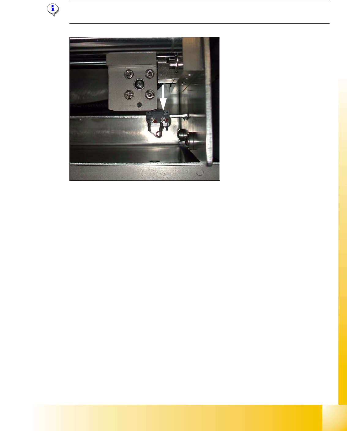
9.2.4.1 Adjusting the limit switch for initialize the driver
Please Note: This is only necessary in case of replacement of the switch or other mal functions
in width adjustment reference run.
Fig. 9.2 - 8 Limit /initialize switch
➠ Move the driver for the width adjustment by hand (via the toothed belt) to the conveyor rail.
➠ Loosen both screws of the limit switch (arrow in Fig. 9.2 - 8)
➠ Move the limit switch in the slot towards the driver and make sure, that the limit switch is safely
switched on.
➠ Check the status of the associated LED on the conveyor control (H41 ini TSP 301) .
➠ Fit the limit switch in this position.
➠ Calibrate the conveyor width via the SITEST program.
1 - 20
Student Guide SIPLACE HF/HF3
9 Modular conveyor Edition 09/2005
20
9.2.5 Width adjustment unit (Driver)
9.2.5.1 Setting the BERO on the driver
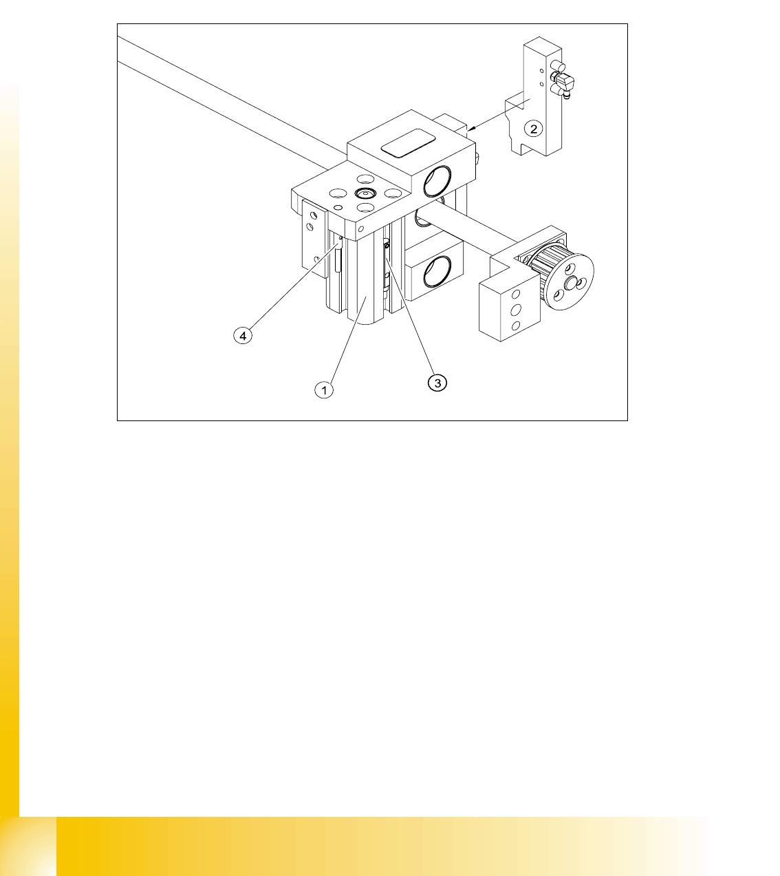
The BERO (3) (see Fig. 9.2 - 9) provides a signal for controlling the pneumatic valve of the driver.
Once the switching point ’conveyor rail reached’ is reached, the pneumatic valve engages the
conveyor rail.
Fig. 9.2 - 9 Overview of the BEROs on the driver for width adjustment
Legend to Fig. 9.2 - 9:
Setting Bero and actuator for transport rail position: 9
➠ When the BERO (4) is installed, it must not protude the driver.
➠ The switching point is set via the actuator on the conveyor rail
➠ Move the driver under the conveyor rail, then loosen the actuator using the screw.
➠ Place the driver at the final dimension of 2/10 mm, press the actuator onto the final dimension
and fix with the screw.
➠ Actuators on all conveyor rails have to be checked and maybe adjusted.
➠ Start SITEST and Calibrate transport.
(1) Short stroke cylinder (2) Solenoid valve
(3) BERO, pneumatic cylinder extended pos. (4) BERO, driver for transport rail position
1 - 21
Student Guide SIPLACE HF/HF3
Edition 09/2005 9 Modular conveyor
21
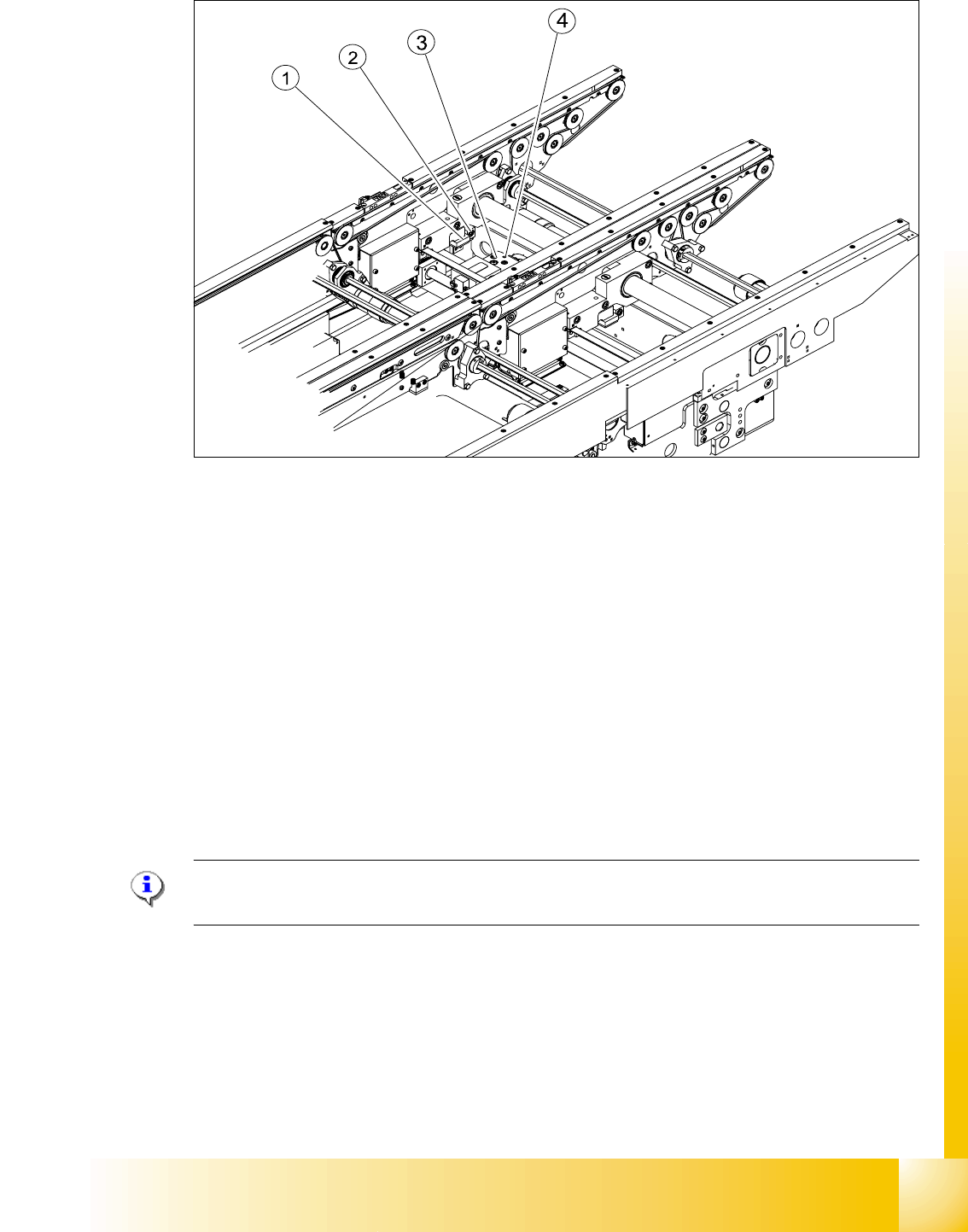
Fig. 9.2 - 10 Setting the actuator block for the width adjustment
Legend
➠ This setting must be repeated for all the conveyor rails.
9.2.5.2 Setting the ’pneumatic cylinder BERO’ on the driver
The BERO (3) (see Fig. 9.2 - 9) on the driver cylinder is designed to switch when the pin of the
driver is extended by the pneumatic cylinder so that the conveyor rail is engaged. This signal en-
ables the width adjustment motor.
Procedure: 9
Please Note:
The BERO on the pneumatic cylinder is set in the engaged state (but not in the free space!).
➠ Start SITEST
➠ Set any conveyor width. This moves the drivers directly under the conveyor rail.
➠ Start the I/O menu.
➠ Activate the pneumatic cylinder.
➠ Set the BERO on the pneumatic cylinder so that the LED (H35/H36/H37 TSP 301) lights up in
the engaged state (see Fig. 9.2 - 9).
(1) Actuator (2) Actuator fixing screw
(3) Driver (4) BERO, driver Transport rail position