SG_FSE_SiplaceHF_HF3_00193901-05_eng.pdf - 第413页
1 - 27 S tudent Guide SIPLACE HF/HF3 Edition 09/2005 9 Modular conveyor 27 9.2.10 Option PCB clamping without clamping sensor Please Note: The check whether a PCB is clamping correctly , is controlled wit h a moto r curr…
1 - 26
Student Guide SIPLACE HF/HF3
9 Modular conveyor Edition 09/2005
26
9.2.9 Adjusting the PCB clamping sensor
Please Note: Not for the X-Series machine!
The force sensor is not used since HF3 is introduced. The clamping of the PCB boards is recog-
nized with a check of the transport motor current (see chapter chapt.9.2.10).
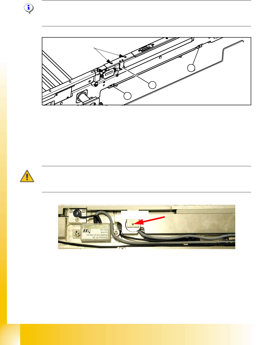
Fig. 9.2 - 15 Clamping sensor for HF machine until Ma.No.xx, and not installed on HF3 machine
The clamp actuators (2), (3) are set so that the actuator (2) nearest to the clamping sensor (1)
responds first. To set the clamping sensor, first loosen the grub screw (see Fig. 9.2 - 15), then push
the grub screw in lightly.
Use Loctite 241. The maximum torque is 2,5 Ncm.
The clamping sensor input must respond to a slight pressure with the thumbs on the grub screw.
(
Sitest -> I/O menu 3 Conveyor 1 or I/O menu 4 Conveyor 2)
Attention
The piezo sensor can be damaged if the grub screw is tightened too far.
Use Loctite 241. The maximum torque is 2,5 Ncm!!
Fig. 9.2 - 16 Clamping sensor
Check: 9
The clamping sensor functions are checked with and without a PCB over the entire conveyor width
to ensure that it is not being affected by any unevenness at the lifting table plate. The clamping
sensor setting is checked with the lifting table running continuously.
An error message appears if the clamping sensor does not respond to the raised lifting table.
1
3
2
max 40Ncm!
Grub screw for setting the
clamping sensor
2,5Ncm!
1 - 27
Student Guide SIPLACE HF/HF3
Edition 09/2005 9 Modular conveyor
27
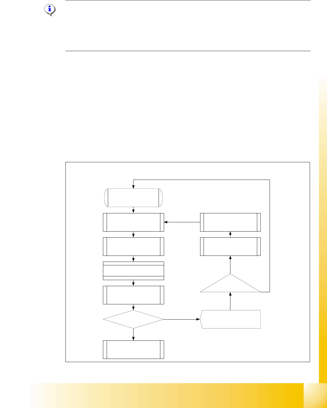
9.2.10 Option PCB clamping without clamping sensor
Please Note:
The check whether a PCB is clamping correctly, is controlled with a motor current check of the
transport motor if the PCB board is clamped (Lifting table up). For check the function you could
put a distance plate under the conveyor rail, that the lifting table can not move to upper position.
This check of PCB clamping is switched OFF, when you have activate the clamping sensor or the
option ceramic substrate centering is installed.
Function describtion: 9
– The PCB moves into the placement area, it is recognized by the light barrier, stops at the laser
and the lifting table moves up.
– Check PCB clamping: The transport motor in the placement area start again. Is the PCB clam-
ped correctly the motor current rise up and reach an defined threshold value. The motor is
stopped and placement process starts.
– If the motor current don‘t reach the threshold value, the PCB board is not clamping correctly.
– On the station computer a error message appears. With the "Start" - button you could repeat
the procedure with "Cancel" the PCB board moves to the output conveyor.
– The lifting table moves down, the PCB board moves back in the placement area and move to
the laser again clamp the board and check it again.
Fig. 9.2 - 17 Flow diagram Check PCB clamping
Threshold value motor
current reached?
Start
PCB board move in the
placement area
Description of the function Check the PCB
board clamping
PCB is recognized by the light
barrier ==> activated the LASER
and start the travel profile
Brake application
LP stops at the LASER and the
lifting table moves up
Start Placement process
Check the clamping
Start Transport motor in the
placement area again
PCB clamping correctly?
Lifting tablr moves down
==> clamping open
PCB moves back and the
prozedure will be repeat
Station computer Error message
"Clamping error transport"
Start-Button
Cancel
YES
NO
1 - 28
Student Guide SIPLACE HF/HF3
9 Modular conveyor Edition 09/2005
28
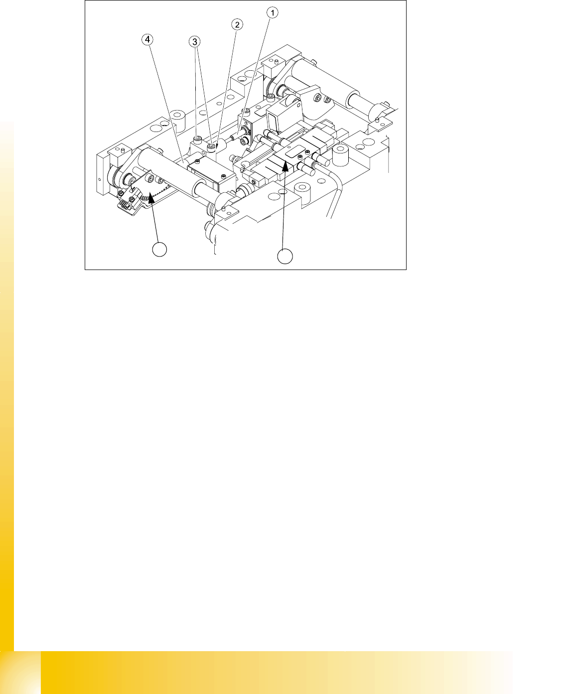
9.2.11 Lifting table functions
Fig. 9.2.18 Lifting table unit
Legend
Lifting table up function 9
Requirements for detecting that the lifting table is up:
1. 7-8 increments on the incremental encoder
2. Clamping sensor (force sensor) (not used in future see chapter chapt.9.2.10)
3. Dynamic response of approx. 500 ms
Lifting table down function 9
Requirements for detecting that the lifting table is down:
1. 7-8 increments on the incremental encoder
2. BERO on the lifting table cylinder
3. Dynamic response of approx. 480 ms
(1) Actuator lifting table drive (2) Lock nut damper
(3) Fixing screws damper bloc (4) adjustable damper
(5) 3/5 way solenoid valve mounted on lifting
table drive cylinder
(6) Fork-type light barriers / incremental disk
5
6