SG_FSE_SiplaceHF_HF3_00193901-05_eng.pdf - 第419页
1 - 33 S tudent Guide SIPLACE HF/HF3 Edition 09/2005 9 Modular conveyor 33 9.2.12 Checks af ter mechani cal work on the conveyor 1. Check: Distance betw een the top edge of the conveyor belt and th e top stop. This value…
1 - 32
Student Guide SIPLACE HF/HF3
9 Modular conveyor Edition 09/2005
32
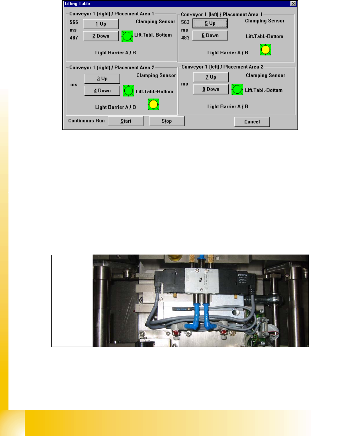
➠ Choose the lifting table which you would check and press the button UP and DOWN.
1. The time for up and down appears in front of the button.
2. If the lifting table move up appears a red light for a short time.
3. Sign (LED on the pneumatic cylinder)for move down the lifting table
4. Sign for move up the lifting table. (Incremental encoder--> Number of the steps were counted
correct)
➠ Adjust the valve on the lifting table cylinder, so that you get the following values:
– Lifting table up: 500 +/- 20ms (
~450 +/-20ms DT / ~360 +/-20 ms ST without lifting table plate)
– Lifting table down: 480 +/- 20ms (
~360 +/-20ms DT / ~ 600 +/-20ms ST without lifting table plate)
➠ Set the lowering speed according the processing needs of your placed PCB.
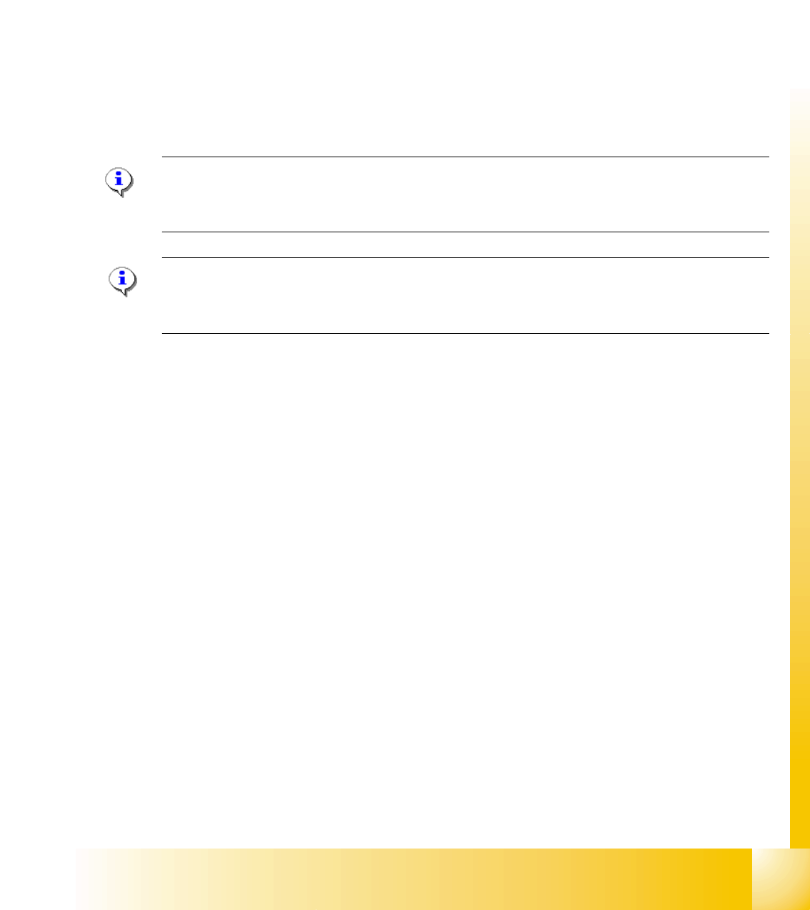
(1)Cylinder drive rod (2) 3/5 solenoid
(3) adjust valve downwards (4) adjust valve upwards
Setting valve anticlockwise: Decrease the lifting table moving time
Setting valve clockwise: Increases the lifting table moving time
1
2
3
4
(2)
(4)
(3)
(1)
1 - 33
Student Guide SIPLACE HF/HF3
Edition 09/2005 9 Modular conveyor
33
9.2.12 Checks after mechanical work on the conveyor
1. Check: Distance between the top edge of the conveyor belt and the top stop.
This value should be
6 mm .
2. Check: Distance between the top edge of the conveyor belt and the top stop, at the clamping
sensor.
This value should be
5.8 mm.
3. Check: Distance between clamping actuator (lifting table) and top edge of the belt.
This value should be
94.2 mm on the HF and HS-60.
4. Check: Distance between clamping actuator (lifting table) and top edge of belt at the clamping
sensor.
This value should be
94.4 mm on the HF and HS-60.
Note for machine with clamping sensor:
The actuator must be seated 0.2 - 0.3 mm deeper below the clamping sensor to ensure that the
piezo sensor (force sensor) is triggered reliably.
Please Note: for machine without clamping sensor:
The distance between clamping actuator (lifting table) and top edge of the belt should be on all
four positions 94,0mm.
1 - 34
Student Guide SIPLACE HF/HF3
9 Modular conveyor Edition 09/2005
34
9.3 Conveyor control
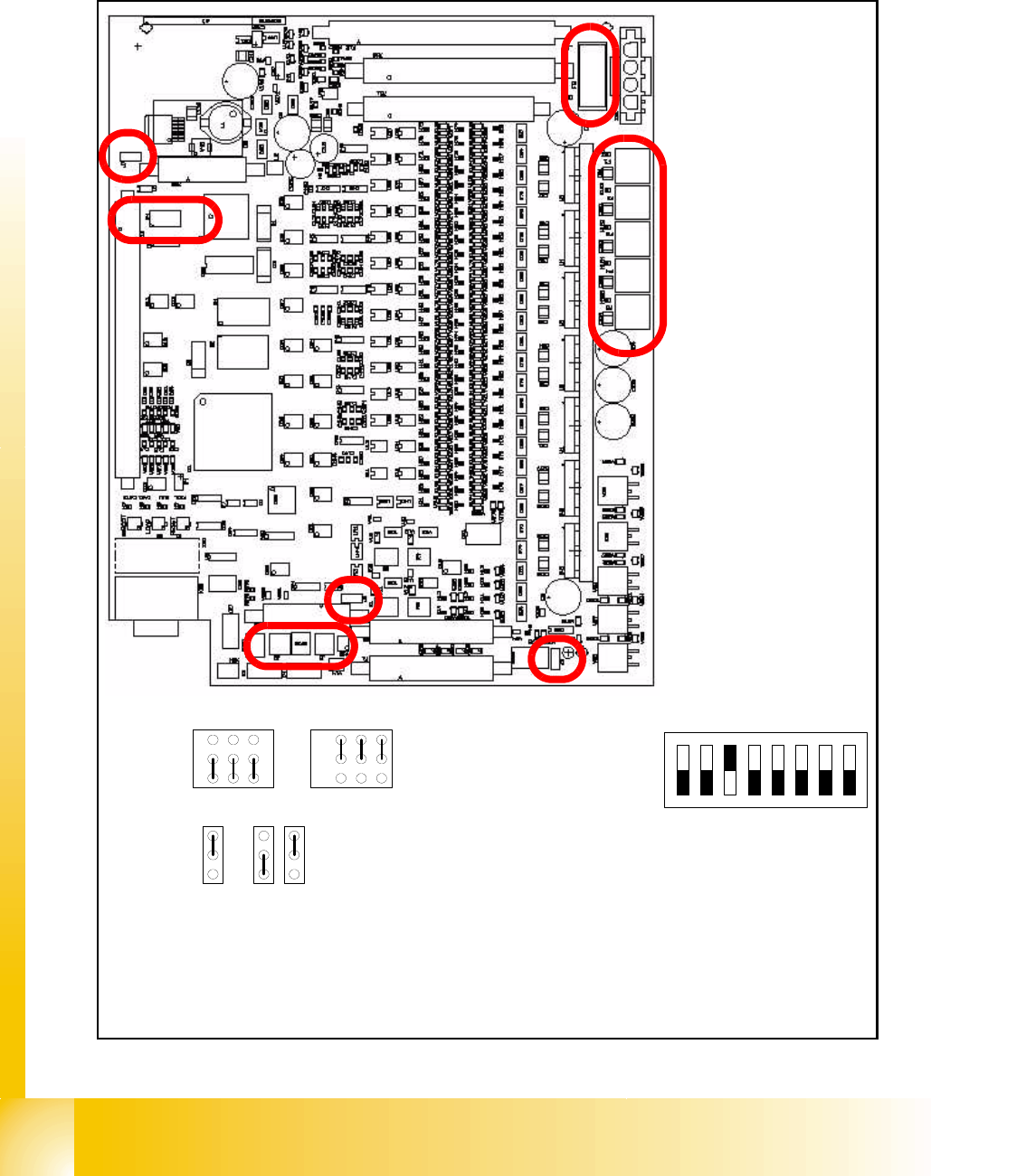
9.3.1 TSP 301 transport control for HF
Fig. 9.3 - 1 Jumper setting for TSP 301 conveyor control
J1 / J2J1 / J2
Siemens SMEMA
1
2
3
J3 J6 J7
3
2
1
3
2
1
OFF
78
ON
123456
DIL Switch S4
J1 Previous station
J2 Next station
J3 Interference loop
J6 CAN bus 1 Terminator (not used)
J7 CAN bus 2 Terminator
S4 DIL switch:
1-OFF = Siplace HS-60
2-OFF = Not used
3-ON = Clamping sensor active
*
3-OFF = Clamping sensor deactivated
4-8 OFF = Not used
* depend on the machine equipment
J3
J2
J1
S4
J7
J6
F6 Main Fuse TSP301
F1 - F5 Fuses for the
conveyor motors