SG_FSE_SiplaceHF_HF3_00193901-05_eng.pdf - 第438页
1 - 10 S tudent Guide SIPLACE HF/HF3 10 Sitest Edition 09/2005 10 10.2.1 Calibration in general Fig. 10.2 - 1 General sequence to calibrate the machine Note: Since the head modularity conce pt means that either a T w in …

1 - 9
Student Guide SIPLACE HF/HF3
Edition 09/2005 10 Sitest
9
10.2 Calibration
WARNING
During some of the procedures the gantries will traverse.
Therefore, before you begin with any of these procedures make sure that you and everyone else
stay physically clear of the travel range of the gantries.
RISK OF INJURY!
Also, ascertain, that no objects are in the way. 10
10
Note:
Before you begin with the calibration, you must reference the heads and the gantries.
During calibration, unused gantries will automatically be traversed to their parking position.
For a complete calibration of the placement system, the SITEST test program provides the func-
tion
"Calibrate machine..." which allows you to start all calibration functions from the menu "Calibrate
entire machine".
Calibration functions will be performed for these functions, for gantries 1, and 2. 10
Equipment and Testing Tools
– Test program SITEST, version 504.xx
– Calibration tools
– Nozzles, type 956, 517,518
– Gauge
– PCB, width 100 mm
1 - 10
Student Guide SIPLACE HF/HF3
10 Sitest Edition 09/2005
10
10.2.1 Calibration in general
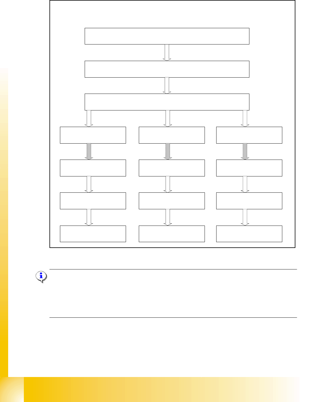
Fig. 10.2 - 1 General sequence to calibrate the machine
Note:
Since the head modularity concept means that either a Twin Head or a C&P head can be fitted to
each gantry, the functions displayed for processing area 1(PA1) and processing area 2 (PA2) re-
spectively may vary. The functions described for PA1 and PA2 below apply for a Twin Head con-
figured on gantry 2 and a C&P head configured on gantry 1.
Sequence of calibrate the HF/HF3 machine with SW 505
Preperation the machine
All heads and cameras..
Sitest: Button "Calibrate machine...."
Calibrate and teach
of positions
PCB Mapping
Head Mapping
Gantry 1
(HF,HF3)
Gantry 3
(HF,HF3)
Calibrate and teach
of positions..
PCB Mapping
Head Mapping
Gantry 4
(HF3)
Calibrate and teach
of positions..
PCB Mapping
Head Mapping
1 - 11
Student Guide SIPLACE HF/HF3
Edition 09/2005 10 Sitest
11
10.2.2 Precondition for calibrate the machine
➠ Start SITEST.
➠ Under menu item "Main view", click "Overall reference run", to reference all gantry- and head-
axes.
➠ Configure the nozzle changer and filling level
➠ Check the zero point correction D-Axis Twin head
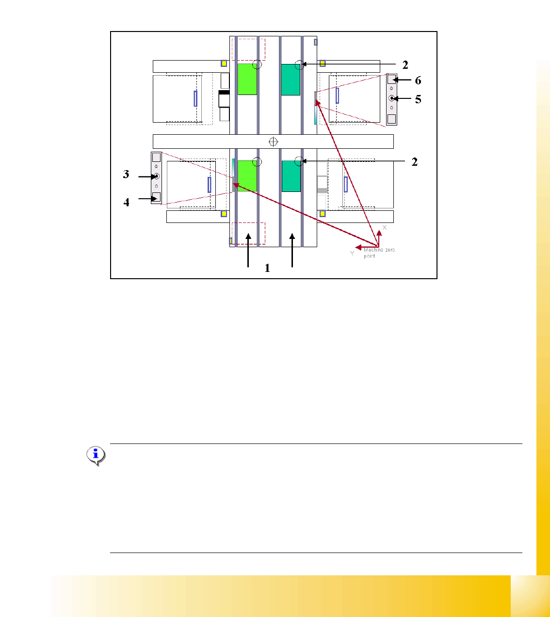
Fig. 10.2 - 2 Top view of machine
Key:
(1) Transport direction
(2) Fixed PCB corner BB 1/ 2 Track 1 and 2
(3) Machine zero point BB 1
(4) Calibration position BB 1
(5) Machine zero point BB 2
(6) Calibration position BB 2
Note:
Some calibrations require that you attach nozzles on the placement heads.
Use nozzles of type
956 and for the Twin head 517. Make sure that all nozzles have been attached
correctly, otherwise measuring will lead to incorrect results.
If you need to, place the calibration tool into the "calibration pocket". (Fig. 10.2 - 2).
Before you place the calibration tool, make sure that it is clean. Also, be sure that you insert it into
the "calibration pocket" with its print of the fiducial structure on the bottom. 10