SG_FSE_SiplaceHF_HF3_00193901-05_eng.pdf - 第442页
1 - 14 S tudent Guide SIPLACE HF/HF3 10 Sitest Edition 09/2005 14 10.2.3.2 T win head Fig. 10.2 - 5 Sequence T win head calibratio n Sequence of c alibrate the Twin head Machine ze ro poi nt Cali bration tool positi on P…

1 - 13
Student Guide SIPLACE HF/HF3
Edition 09/2005 10 Sitest
13
10.2.3.1 C&P head
Fig. 10.2 - 4 Sequence C&P head calibration
Ablauf der Kalibrierung des C&P Kopfes
Maschinennullpunkt
Kalibrierteilposition
LP-Kamera
y
Kamera-Koeffizient (Abbildungsmaßstab in nm/pixel)
y
Kalibrierung des LP-Kamera-Mittelpunktes
y
Kalibrierung der Verdrehung der LP-Kamera zum
Maschinen-Koordinatensystem
Verfahrweg X-/Y-Achse
y
Kalibrierung der min/max Verfahrwege der Portale
C&P Kopf
y
Kamera-Koeffizient (Einheit -nm/pixel), Winkel
y
Kopf-Offset (Offset LP-Kamera zu BE-Kamera)
y
Segmentoffset II (unten)
y
Segmentoffset I (oben)
C&P Kopf Pipettenwechsler
y
Kalibrierung der Abholpositionen für alle Magazine
y
Kalibrierung der Abholhöhe
y
Kalibrierung der Abwurfposition
1 - 14
Student Guide SIPLACE HF/HF3
10 Sitest Edition 09/2005
14
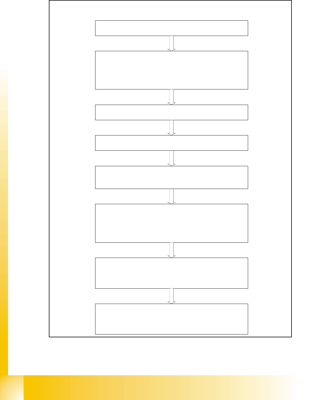
10.2.3.2 Twin head
Fig. 10.2 - 5 Sequence Twin head calibration
Sequence of calibrate the Twin head
Machine zero point
Calibration tool position
PCB camera
y Camera coefficient (image scale -nm/pixel)
y Calibrate the camera center
y Calibrate camera angle to the MA-coordinate system
Travel range X/Y Axis
y calibrate the max and min position of the travel range
Twin head height
y Calibrate the height of the segment 1 and 2 (reference is
the top of the conveyor rail)
Twin head IC-camera
y Focus level
y Camera coefficient (image scale -nm/pixel), Angle
y IC camera position
y IC camera position fiducial
Twin head nozzle changer
y Calibrate the pick up position all magazines
y Calibrate pick up height
y Calibrate reject position
Twin head
y Head offset Segment 1 (PCB camera to Segment 1)
y Head offset Segment 2 (PCB camera to Segment 2)
1 - 15
Student Guide SIPLACE HF/HF3
Edition 09/2005 10 Sitest
15
Machine zero point: 10
– The PCB-camera center is the reference at the gantry. All positions at the incremental encoder
of X/Y-axis refer to this camera center.
– A drilling is optically centered with the PCB-camera on a defined position at the calibration tool
support.
– Than the Zero point correction of the gantry axes are changed that if the PCB camera is above
this hole and the Positioncounter shows exactly the value of:
MA nullpunkt_x_PG1 631300 / MA nullpunkt_y_PG1 1298000. ( pg means gantry group)
MA nullpunkt_x_PG2 1368700 / MA nullpunkt_y_PG2 702000 ( See Fig. 10.2 - 2)
PCB camera: 10
– the Pixel size of the CCD sensors of the camera is determined in µm. Measured and calcu-
lated with Ax/Bx/Ay/By calibration values. Saved in KAM_DAT.MA as:XU_Pixel / YU_Pixel
(in 11600 nm Standard-PCB camera SST 5), (in 9900 nm Multicolorillum. PCB camera SST 18)
– The camera center is determined.
– This camera center is now the reference for all Position and Offsets of the gantry!!
– The Mounting angle of the CCD-chip in the camera to the Ma-coordinate system. Saved as
‘Kamera_winkel’ at the Data bloc of the PCB camera in KAMDAT.MA.
Calibration tool position:(optional) 10
– Calibrate the X and Y pick up position of the calibration tool.
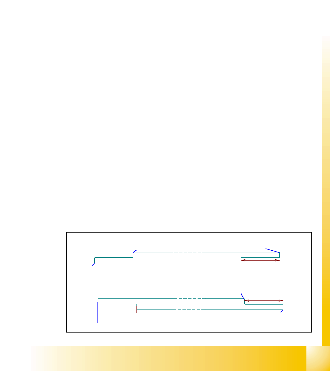
Travel range:(optional) 10
– For travel range calibration move the respective axis: -to the Zero-pulse
– Then to the Hardware-limit switch
– Measure the position value at the position counter
– Calculate the position for SW-limit switch (Y +/- 1.5 mm , X +/- 0,5 mm)
65mm
Wendepunkt für Referenzla uf
G esc hwindigke itsüberwac hung
HW- Endsc ha lter
Y-Ac hse
45mm
X-Achse
G esc hwindigkeitsüberwac hung
HW-Endsc ha lter
HW- Endsc ha lter
G esc hwindigke itsüberwac hung
We nd e p unk t für Re fe re nzla uf
Gesc hwindigkeitsüberwac hung
HW- Endsc ha lter