SG_FSE_SiplaceHF_HF3_00193901-05_eng.pdf - 第449页
1 - 21 S tudent Guide SIPLACE HF/HF3 Edition 09/2005 10 Sitest 21 10.2.4.4 Pick up position (Calibrate the comp onent t able T rack 1- 90) Determines the X and Y positions for the ta ble 1up to 4 with the relevant tr ack…

1 - 20
Student Guide SIPLACE HF/HF3
10 Sitest Edition 09/2005
20
10.2.4 Calibrate and teach machine positions
New function for calibrate the positions is the teach menue before calibrate, so that you can teach
the correct position for a successfully calibration.
10.2.4.1 Conveyor edges (Conveyor rails)
This new calibration procedure is necessary for the modular conveyor system.
With the modular conveyor are all conveyor rails adjustable. For adjustment the conveyor rails we
use one stepper motor which is connected via a toothed belt to the driver unit. The position of the
rails are recognize with a BERO and therefore we have different switch point on each conveyor
rails. With this calibration the switch points are optimized of the entire travel range of the width
adjustment. The calibration is necessary that all three Driver units move the conveyor rails paral-
lel.
Automatically Sequence (Transport mapping):
– Initialize the driver unit, move to the right side (limit switch)
– Driver unit recognize the fixed conveyor rail (rails dual conveyor) move the conveyor rails a
standard position of 55mm.
– The driver unit move the moveable conveyor rail step by step (10mm steps) and determined
the offset of the rail positions for the three drivers.
– This calibration of the rail position will be done for width adjustment wider and smaller.
– The results are saved in the conveyor controller as correction values and taken into account
later when setting and measuring the conveyor width.
Note:
The calibration must be done for Track 1 and Track 2.
10.2.4.2 Conveyor width calibration
The conveyor width calibration determine the width with a 100mm wide standard PCB board.
10.2.4.3 PCB reference corner
– Select gantry 1 or 2.
– Select PCB reference corner position right or PCB reference corner position left (dual con-
veyor)
– Moves the active gantry with the PCB camera over the reference corner position and switches
the screen display to the PCB camera for checking purposes.
The reference corner position is visible in the camera's field of view. Teaching mean now the
camera center is to align with the right corner of the PCB.

1 - 22
Student Guide SIPLACE HF/HF3
10 Sitest Edition 09/2005
22
10.2.5 PCB mapping
With the PCB mapping the linearity of the X- and Y-guidance for PCB-camera movement is mea-
sured in the placement area.
The PCB-camera center the cross fiducials on a high precise glass plate. This glass plate is cali-
brated with a measurement machine and this data´s are considered in the measurement se-
quence.
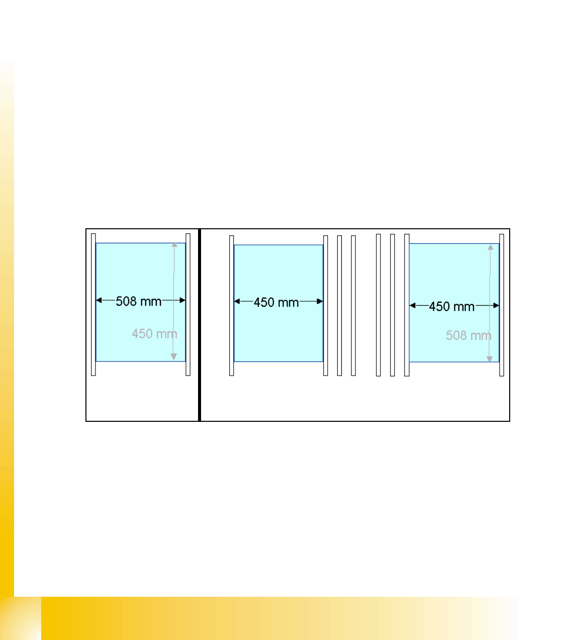
Preperation mapping: 10
➠ At the single conveyor the SITEST move the transport rails to 508mm wide the mapping plate
is 90 degree turned.
➠ At dual conveyor the SITEST SW move all the transport rails depend of the track which is se-
lected the conveyor for mapping to 450 mm wide the other track to 0mm. This allow to used
the Dual conveyor as a single conveyor. The Mapping must be carried out for the maximum
conveyor width.
➠ To prepare the PCB and RV Mapping the SITEST SW move automatically the Transport rails
that the mapping plate fit to the the referring track.
➠ The C&P Heads have to have 956 nozzles the TWIN have to have 517 nozzles for mapping.
➠ The calibration tools are in the calibration pocket.
Fig. 10.2 - 10 Position mapping plate and conveyor rail position for single and dual conveyor
Procedure: 10
➠ insert the mapping disk at the station computer to prepare and copy the nominal data for this
individual mapping plate.
➠ Put the mapping plate in the input conveyor for placement area 1 or in the intermediate con-
veyor for placement area 2.
➠ Now appears the teach menue to teach the fixed PCB corner OK.
➠ PCB mapping is running.
Single conveyor
Dual conveyor
Track 2 Track 1