SG_FSE_SiplaceHF_HF3_00193901-05_eng.pdf - 第450页
1 - 22 S tudent Guide SIPLACE HF/HF3 10 Sitest Edition 09/2005 22 10.2.5 PCB mapping With the PCB mappin g the linearity of the X- and Y -guidance for PCB-camera movement is mea- sured in the place ment area. The PCB-cam…

1 - 22
Student Guide SIPLACE HF/HF3
10 Sitest Edition 09/2005
22
10.2.5 PCB mapping
With the PCB mapping the linearity of the X- and Y-guidance for PCB-camera movement is mea-
sured in the placement area.
The PCB-camera center the cross fiducials on a high precise glass plate. This glass plate is cali-
brated with a measurement machine and this data´s are considered in the measurement se-
quence.
Preperation mapping: 10
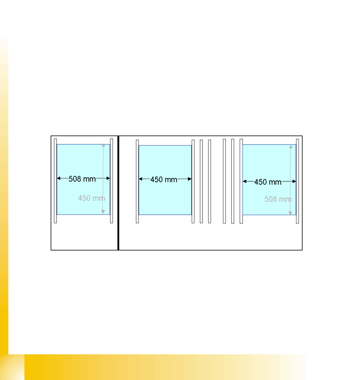
➠ At the single conveyor the SITEST move the transport rails to 508mm wide the mapping plate
is 90 degree turned.
➠ At dual conveyor the SITEST SW move all the transport rails depend of the track which is se-
lected the conveyor for mapping to 450 mm wide the other track to 0mm. This allow to used
the Dual conveyor as a single conveyor. The Mapping must be carried out for the maximum
conveyor width.
➠ To prepare the PCB and RV Mapping the SITEST SW move automatically the Transport rails
that the mapping plate fit to the the referring track.
➠ The C&P Heads have to have 956 nozzles the TWIN have to have 517 nozzles for mapping.
➠ The calibration tools are in the calibration pocket.
Fig. 10.2 - 10 Position mapping plate and conveyor rail position for single and dual conveyor
Procedure: 10
➠ insert the mapping disk at the station computer to prepare and copy the nominal data for this
individual mapping plate.
➠ Put the mapping plate in the input conveyor for placement area 1 or in the intermediate con-
veyor for placement area 2.
➠ Now appears the teach menue to teach the fixed PCB corner OK.
➠ PCB mapping is running.
Single conveyor
Dual conveyor
Track 2 Track 1
1 - 23
Student Guide SIPLACE HF/HF3
Edition 09/2005 10 Sitest
23
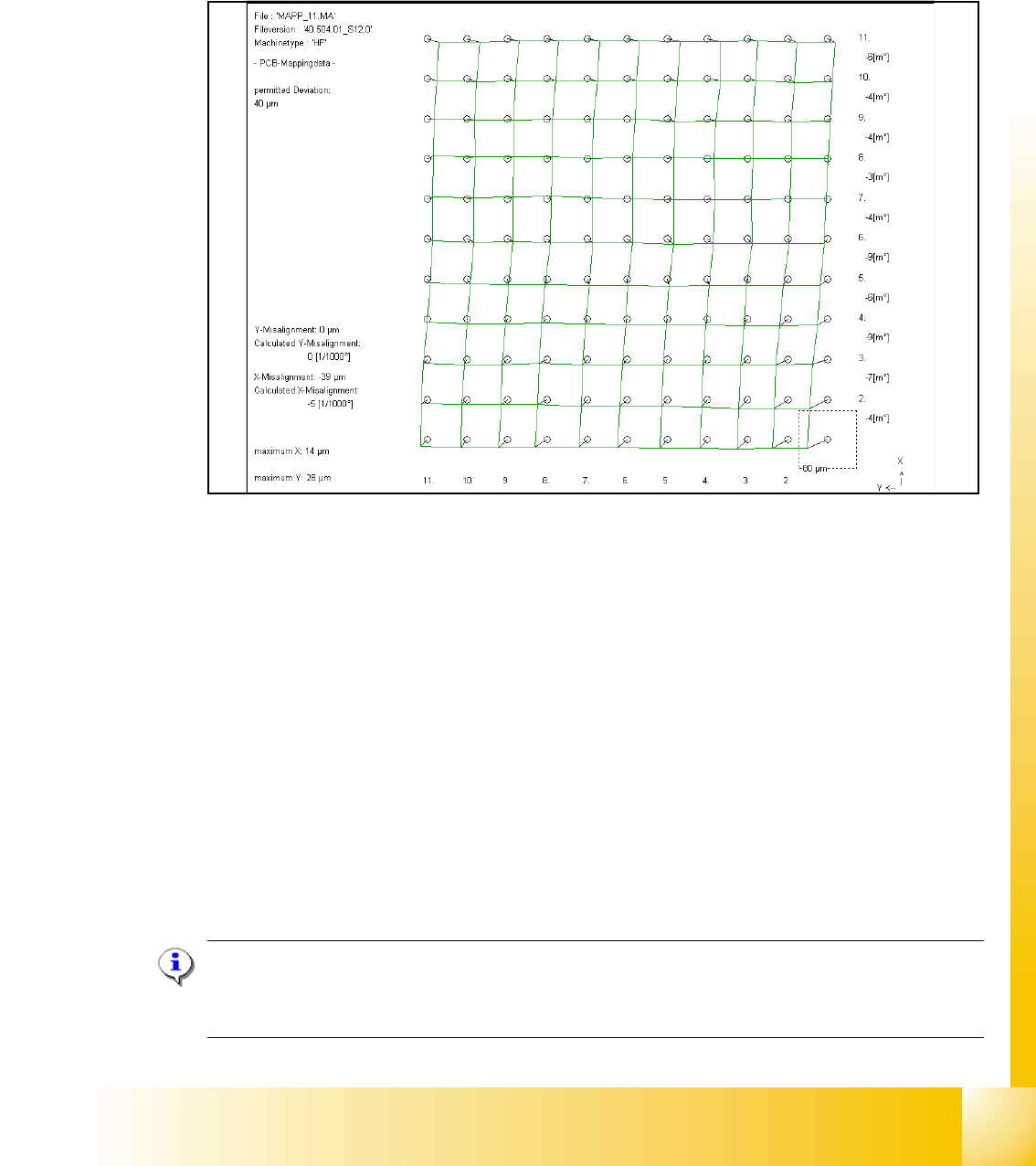
➠ Then the gantry axes move the camera up to the start position. This is centered according to
the synthetic picture of the bright cross structure at this position.
➠ This results are set for the nominal coordinates. 40.000 µm in X- respectively Y- direction
added for the next fiducial nominal position.
➠ The deviation of the structure to this theoretical position is measured.
Fig. 10.2 - 11 Result of PCB mapping
The result are saved in the mapp _xy.ma ( x= number of the gantry , y= transport track)
10.2.6 Head mapping( C&P,Twin head)
With the head mapping the linearity of the X- and Y-guidance for C&P head movement is mea-
sured in the placement area.
The C&P head place the calibration tool on the mapping glass board exact to the nominal posi-
tions of the glass plate. The PCB-camera measure the placement accuracy of this placements for
the whole placement area.
➠ After the PCB mapping the placement head place at the theoretical positions of the PCB-map-
ping the calibration tool.
➠ The PCB-Camera look for the placement accuracy on the 4 fiducials at the calibration tool cor-
ner.
Note:
All described automatically calibration steps above, can you do manually step by step under the
sub menus (see chapter 12.1).