SG_FSE_SiplaceHF_HF3_00193901-05_eng.pdf - 第47页
1 - 21 S tudent Guide SIPLACE HF/HF3 Edition 09/2005 2 Overview 21 2.2.8 Component changeover t able 2.2.8.1 Docking and Undocking The c hangeo ver t able (C OT) will be docking and undocking automatically with 2 pneumti…
1 - 20
Student Guide SIPLACE HF/HF3
2 Overview Edition 09/2005
20
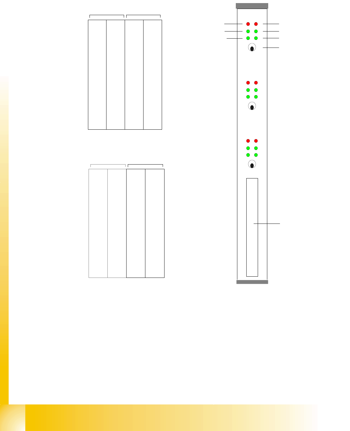
2.2.7.3 Axis Card A363
Abbreviation:
X = X-Axis and Gantry number
Z1=Z-Axis for Twin head Modul 1
Y= Y-Axis and Gantry number D
1=turning Axis for Twin head Modul 1
S= Star Axis and Gantry number for C&P head Z
2=Z-Axis for Twin head Modul 2
Z= Z-Axis and Gantry number for C&P head D
2=turning Axis for Twin head Modul 2
DP= Swivel Axis and Gantry number for C&P
head
Counter error
Zero puls
End signal
Common error,
Board error
Initialisation
Servo On
Axis switch off/on
Axis 0
Axis 1
Axis 2
Interface
Axis test box
X 1
Address
0
Y 1
Address
1
S 1
Address
2
Z 1
Address
3
DP 1
Address
5
free
Address
5
X 4
Address
6
Y 4
Address
7
S 4
Address
8
Z 4
Adress
9
DP 4
Address
10
free
Address
11
Gantry 1 Gantry 4
Placement area PA 1
Servos 'bottom'Servos 'top'
X 2
Address
16
Y 2
Address
17
S 2
Address
18
Z 2
Address
19
DP 2
Address
20
free
Address
21
X 3
Address
22
Y 3
Address
23
S3/Z
2
Address
24
Z/Z
1
Address
25
DP/D
1
Address
26
/D
2
Addres
27
Gantry 2 not used Gantry 3
Placement area PA 2
Servos 'bottom'Servos 'top'
1 - 21
Student Guide SIPLACE HF/HF3
Edition 09/2005 2 Overview
21
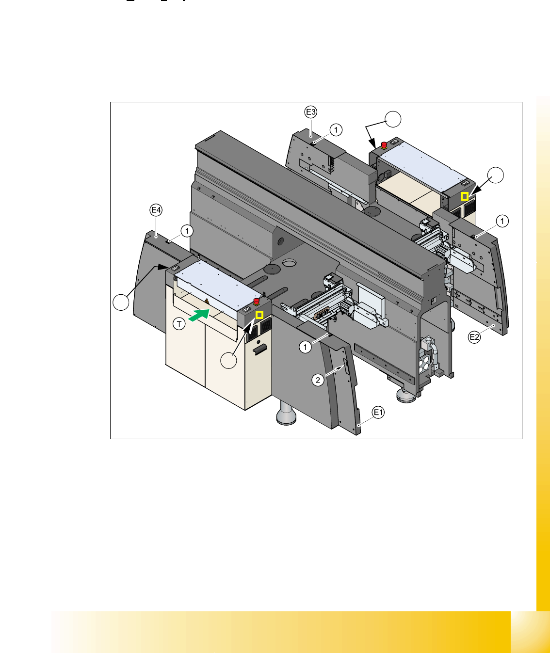
2.2.8 Component changeover table
2.2.8.1 Docking and Undocking
The changeover table (COT) will be docking and undocking automatically with 2 pneumtic cylin-
ders, which are arranged on the left and right side on the machine frame. For docking the COT
move the table to the machine press the button 1 and 2 (Two hand operation). For undocking the
COT open the cover and press the button 1.
A one hand operation (one button) for docking and undocking the COT come with HF machine
version ’A’.
Fig. 2.2 - 11 Shows the buttons for docking and undocking the COT‘s
Each table has fifteen slots for 8 mm SIPLACE feeders.
Therefore a total capacity of 180 tracks for 8mm tapes, if you used 4 component tables.
(1) Button "Undocking Changeover table"
(2) Button "Docking Changeover table --> Two hand operation together with Button 1
(3) Button "Docking Changeover table --> one hand operation Machine version ’A’
(E1-E4) Sector1 - Sector 4
3
3
3
3
1 - 22
Student Guide SIPLACE HF/HF3
2 Overview Edition 09/2005
22
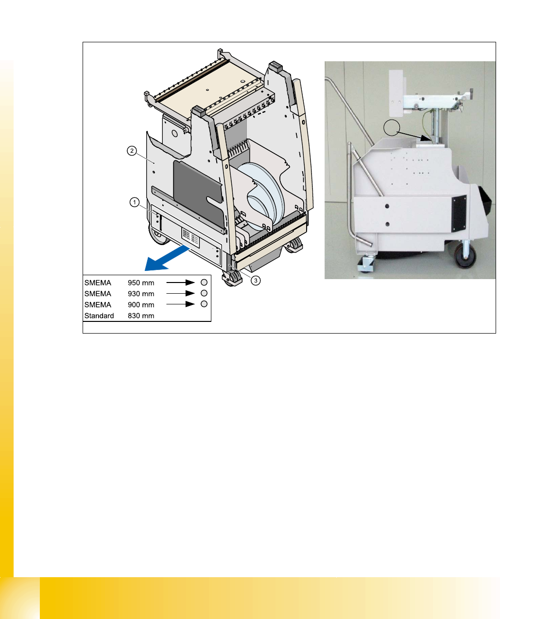
2.2.8.2 Adjust the changeover table height
The COT can be prepared for the following PCB transportation heights by hand.
– 830 mm ± 15 mm Standard-height
– 900 mm ± 15 mm SMEMA-height
– 930 mm ± 15 mm SMEMA-height
– 950 mm ± 15 mm SMEMA-height
Fig. 2.2 - 12 COT with Transport height 950 mm
(1) Pins for showing the height (2) Upper part of the COT
(3) trolley (bottom part )of COT (4) here height adjustment of COT version ’A’
All height marking pins disappear at the standard transportation height of 830 mm under the side
of the upper part of the COT .If the upper part of the COT is lifted, the marking pins will be press
out by a spring. The upper part of the COT lain on these marking pins.
4