SG_FSE_SiplaceHF_HF3_00193901-05_eng.pdf - 第473页
S tudent Guide SIPLACE HF/HF3 Edition 09/2005 Contents 1 Chapter T able of Content s 11 MTC 2 . . . . . . . . . . . . . . . . . . . . . . . . . . . . . . . . . . . . . . . . . . . . . . . . . . . . . . . . . . . . 1 11.1…
1 - 44
Student Guide SIPLACE HF/HF3
10 Sitest Edition 09/2005
44
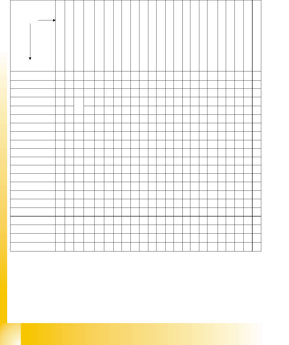
10.2.9.3 Adjustment - and Calibration tools
adjust - and
calibration tools
adjust and
calibration jobs
Machine types
(without S15/F3)
Digital Manometer 00311487 -01
Digital Manometer with analouge-cable for
S15/F3 00313523 -01
Track signal tester for S/F 00322510-02
Adapter cable track signal tester f. F5HM/S27HM
00360395-01
Track signal tester for HS/HF 00343785-01
Belt tension meter TSM 00326015-01
Axis test box Vers.6 00303430-06 alternatively to
SAT
SIPLACE Axis Tester SAT 03002801-01
RC-Filter 02102858-01
0,2mm distance gauge 00325445-01 from gauge
set 00327005-01
Star-0-point.gauge 00326164-01 from gauge set
00327005-01
power supply for Star mounting DLM-heads
00353277-01
1.1 mm pin (replace 1.3mm pin from gauge set
00327005-01)
1,4; 1,5; 1,6mm pins from gauge set 00327005-
01
gauge Z-axis stop top 00331308-01
Test connector safety loop coplan ILD 2000
00337304-01
calibration tool coplan 00315365-03
calibration tool Vision Version II (clear) 00316308
-
03
calibration tool Vision Version 3 (for hf / white)
03010565-01
calibration nozzle D-zero-point-corr. Twin
03008862-02
I/O-Tester for SXX/FX 00321960-01
wiring test adapter 14 pole 02304826-01
wiring test adapter 34 pole 02304827-01
exchange vacuum distrib./Star/
air kiss unit. All
S15
F3
exchange incremental encoder
gantry
All
S/F
F5HM/S
27HM
HF/
HS
exchange incremental scale
gantry
All
S/F
F5HM/S
27HM
HF/
HS
exchange 'head board' C&P
head
exchange 'conversion board
large axis'
exchange incremental encoder
DP axis All All
exchange lightbarrier bottom
C&P head All
exchange placement star All
All
with
DLM x
exchange Z-motor All All All All
exchange Z-belt All All All All All
exchange Z-top stop All
exchange drive belt /- motor All All All All
exchange coplanarity module All F All F
exchange PCB camera
All
without
. HF
exchange C&P-placement
head
All
without
. HF
exchange component cameras
All
without
. HF
exchange segment Twin-head HF HF
Display I/O-States of the I/O-
Boards
All
S/F
wiring test ribbon cable All All
exchange ballrace only spec.
trained staff
Mapping
All S/F
without
S27/F5
HM

Student Guide SIPLACE HF/HF3
Edition 09/2005 Contents
1
Chapter
Table of Contents
11 MTC 2 . . . . . . . . . . . . . . . . . . . . . . . . . . . . . . . . . . . . . . . . . . . . . . . . . . . . . . . . . . . . 1
11.1 Overview. . . . . . . . . . . . . . . . . . . . . . . . . . . . . . . . . . . . . . . . . . . . . . . . . . . . . . . . . . . . . . . . . . . . . . 1
11.1.1 General Matrix Tray Changer 2. . . . . . . . . . . . . . . . . . . . . . . . . . . . . . . . . . . . . . . . . 1
11.1.2 Functional principles . . . . . . . . . . . . . . . . . . . . . . . . . . . . . . . . . . . . . . . . . . . . . . . . . 2
11.1.3 Occupying and numbering the tower. . . . . . . . . . . . . . . . . . . . . . . . . . . . . . . . . . . . . 4
11.1.4 Technical data. . . . . . . . . . . . . . . . . . . . . . . . . . . . . . . . . . . . . . . . . . . . . . . . . . . . . . 5
11.1.4.1 Dimensions, weight, miscellaneous data . . . . . . . . . . . . . . . . . . . . . . . . . . . . . . 5
11.1.4.2 Electrical connections. . . . . . . . . . . . . . . . . . . . . . . . . . . . . . . . . . . . . . . . . . . . . 6
11.1.4.3 Noise emission information . . . . . . . . . . . . . . . . . . . . . . . . . . . . . . . . . . . . . . . . 6
11.1.4.4 Permitted ambient conditions. . . . . . . . . . . . . . . . . . . . . . . . . . . . . . . . . . . . . . . 6
11.1.5 Safety information . . . . . . . . . . . . . . . . . . . . . . . . . . . . . . . . . . . . . . . . . . . . . . . . . . . 7
11.1.5.1 Warning and information labels on the MTC 2. . . . . . . . . . . . . . . . . . . . . . . . . . 7
11.1.5.2 Safety instructions for transporting the MTC 2. . . . . . . . . . . . . . . . . . . . . . . . . 12
11.1.5.3 Residual voltages at the inverters when the MTC 2 is switched off . . . . . . . . . 12
11.1.6 Safety features . . . . . . . . . . . . . . . . . . . . . . . . . . . . . . . . . . . . . . . . . . . . . . . . . . . . 13
11.1.6.1 Protective doors . . . . . . . . . . . . . . . . . . . . . . . . . . . . . . . . . . . . . . . . . . . . . . . . 13
11.1.6.2 EMERGENCY STOP button. . . . . . . . . . . . . . . . . . . . . . . . . . . . . . . . . . . . . . . 13
11.1.6.3 Protective door switches. . . . . . . . . . . . . . . . . . . . . . . . . . . . . . . . . . . . . . . . . . 14
11.1.6.4 Combination circuit breakers . . . . . . . . . . . . . . . . . . . . . . . . . . . . . . . . . . . . . . 15
11.1.6.5 Safety and signaling circuits. . . . . . . . . . . . . . . . . . . . . . . . . . . . . . . . . . . . . . . 15
11.1.6.6 Safety loops . . . . . . . . . . . . . . . . . . . . . . . . . . . . . . . . . . . . . . . . . . . . . . . . . . . 16
11.2 Construction and mode of operation. . . . . . . . . . . . . . . . . . . . . . . . . . . . . . . . . . . . . . . . . . . . . . 17
11.2.1 Incorporating the MTC in the SIPLACE station. . . . . . . . . . . . . . . . . . . . . . . . . . . . 18
11.2.1.1 CAN bus. . . . . . . . . . . . . . . . . . . . . . . . . . . . . . . . . . . . . . . . . . . . . . . . . . . . . . 18
11.2.1.2 400 V power supply . . . . . . . . . . . . . . . . . . . . . . . . . . . . . . . . . . . . . . . . . . . . . 18
11.2.1.3 EMERGENCY STOP interface. . . . . . . . . . . . . . . . . . . . . . . . . . . . . . . . . . . . . 18
11.2.2 Reference position run . . . . . . . . . . . . . . . . . . . . . . . . . . . . . . . . . . . . . . . . . . . . . . 19
11.2.3 Installation MTC 2 . . . . . . . . . . . . . . . . . . . . . . . . . . . . . . . . . . . . . . . . . . . . . . . . . . 20
11.2.4 Modules of the controller. . . . . . . . . . . . . . . . . . . . . . . . . . . . . . . . . . . . . . . . . . . . . 21
11.2.4.1 C167 controller board. . . . . . . . . . . . . . . . . . . . . . . . . . . . . . . . . . . . . . . . . . . . 22
11.2.4.2 Masterdrives. . . . . . . . . . . . . . . . . . . . . . . . . . . . . . . . . . . . . . . . . . . . . . . . . . . 23
11.2.4.3 24V power supply. . . . . . . . . . . . . . . . . . . . . . . . . . . . . . . . . . . . . . . . . . . . . . . 23
11.2.4.4 Electronics board . . . . . . . . . . . . . . . . . . . . . . . . . . . . . . . . . . . . . . . . . . . . . . . 23
11.2.4.5 Mounting plate . . . . . . . . . . . . . . . . . . . . . . . . . . . . . . . . . . . . . . . . . . . . . . . . . 24
11.2.5 Block diagrams . . . . . . . . . . . . . . . . . . . . . . . . . . . . . . . . . . . . . . . . . . . . . . . . . . . . 25
11.2.6 Installation MTC 2 . . . . . . . . . . . . . . . . . . . . . . . . . . . . . . . . . . . . . . . . . . . . . . . . . . 28
11.2.7 General works before starting the MTC 2 . . . . . . . . . . . . . . . . . . . . . . . . . . . . . . . . 29
11.2.8 Placement functions of the MTC 2 . . . . . . . . . . . . . . . . . . . . . . . . . . . . . . . . . . . . . 29

1 - 2
Student Guide SIPLACE HF/HF3
Contents Edition 09/2005
2
11.2.8.1 Main view with MTC 2. . . . . . . . . . . . . . . . . . . . . . . . . . . . . . . . . . . . . . . . . . . . 29
11.2.8.2 "Matrix-tray changer" view . . . . . . . . . . . . . . . . . . . . . . . . . . . . . . . . . . . . . . . . 31
11.2.9 Single functions of the MTC 2 . . . . . . . . . . . . . . . . . . . . . . . . . . . . . . . . . . . . . . . . . 34
11.2.9.1 "Matrix-tray changer single functions" view . . . . . . . . . . . . . . . . . . . . . . . . . . . 34
11.3 Calibration MTC 2. . . . . . . . . . . . . . . . . . . . . . . . . . . . . . . . . . . . . . . . . . . . . . . . . . . . . . . . . . . . . . 35
11.3.1 Calibration sequence in general . . . . . . . . . . . . . . . . . . . . . . . . . . . . . . . . . . . . . . . 35
11.3.1.1
Terms of calibration lifting axes . . . . . . . . . . . . . . . . . . . . . . . . . . . . . . . . . . 36
11.3.1.2 Terms of calibration feed axes . . . . . . . . . . . . . . . . . . . . . . . . . . . . . . . . . . . . . 37
11.3.2 Sitest calibration flow charts . . . . . . . . . . . . . . . . . . . . . . . . . . . . . . . . . . . . . . . . . . 38
11.3.2.1 Lifting axes . . . . . . . . . . . . . . . . . . . . . . . . . . . . . . . . . . . . . . . . . . . . . . . . . . . . 38
11.3.2.2 Feed axes. . . . . . . . . . . . . . . . . . . . . . . . . . . . . . . . . . . . . . . . . . . . . . . . . . . . . 39
11.3.2.3 Machine data MTC . . . . . . . . . . . . . . . . . . . . . . . . . . . . . . . . . . . . . . . . . . . . . . 46
11.3.3 Adjustments Lifting Axes . . . . . . . . . . . . . . . . . . . . . . . . . . . . . . . . . . . . . . . . . . . . . 47
11.3.3.1 Belt tension. . . . . . . . . . . . . . . . . . . . . . . . . . . . . . . . . . . . . . . . . . . . . . . . . . . . 48
11.3.3.2 Guide rails and stopper bars. . . . . . . . . . . . . . . . . . . . . . . . . . . . . . . . . . . . . . . 51
11.3.3.3 Cassette guide rails . . . . . . . . . . . . . . . . . . . . . . . . . . . . . . . . . . . . . . . . . . . . . 53
11.3.4 Adjustments feed axes . . . . . . . . . . . . . . . . . . . . . . . . . . . . . . . . . . . . . . . . . . . . . . 55
11.3.4.1 Belt tension. . . . . . . . . . . . . . . . . . . . . . . . . . . . . . . . . . . . . . . . . . . . . . . . . . . . 55
11.3.4.2 Limit switch. . . . . . . . . . . . . . . . . . . . . . . . . . . . . . . . . . . . . . . . . . . . . . . . . . . . 57
11.3.4.3 Light barriers. . . . . . . . . . . . . . . . . . . . . . . . . . . . . . . . . . . . . . . . . . . . . . . . . . . 59
11.3.4.4 Checking and setting the WTC safety queries . . . . . . . . . . . . . . . . . . . . . . . . . 61
11.3.4.5 Disengaging mechanism . . . . . . . . . . . . . . . . . . . . . . . . . . . . . . . . . . . . . . . . . 64
11.3.5 Converting the power supply. . . . . . . . . . . . . . . . . . . . . . . . . . . . . . . . . . . . . . . . . . 65
11.3.5.1 Procedure. . . . . . . . . . . . . . . . . . . . . . . . . . . . . . . . . . . . . . . . . . . . . . . . . . . . . 65
11.3.5.2 Voltage distributor terminal X01 . . . . . . . . . . . . . . . . . . . . . . . . . . . . . . . . . . . . 66
11.3.5.3 Motor protection switch. . . . . . . . . . . . . . . . . . . . . . . . . . . . . . . . . . . . . . . . . . . 66
11.3.6 Machine Data. . . . . . . . . . . . . . . . . . . . . . . . . . . . . . . . . . . . . . . . . . . . . . . . . . . . . . 67
11.3.6.1 General machine parameters. . . . . . . . . . . . . . . . . . . . . . . . . . . . . . . . . . . . . . 67
11.3.6.2 Machine parameters for tower 1. . . . . . . . . . . . . . . . . . . . . . . . . . . . . . . . . . . . 67
11.3.6.3 Machine parameters for tower 2. . . . . . . . . . . . . . . . . . . . . . . . . . . . . . . . . . . . 69
11.3.7 Spare parts list for MTC1. . . . . . . . . . . . . . . . . . . . . . . . . . . . . . . . . . . . . . . . . . . . . 72
11.4 Masterdrives. . . . . . . . . . . . . . . . . . . . . . . . . . . . . . . . . . . . . . . . . . . . . . . . . . . . . . . . . . . . . . . . . . 75
11.4.1 Operating the master drive with the parametrization unit (PMU). . . . . . . . . . . . . . . 75
11.4.2 Important Parameter for trouble shooting . . . . . . . . . . . . . . . . . . . . . . . . . . . . . . . . 76
11.4.3 Factory settings . . . . . . . . . . . . . . . . . . . . . . . . . . . . . . . . . . . . . . . . . . . . . . . . . . . . 77
11.4.4 Setting the CAN bus address at the master drive PMU. . . . . . . . . . . . . . . . . . . . . . 78
11.4.5 Downloading parameter sets. . . . . . . . . . . . . . . . . . . . . . . . . . . . . . . . . . . . . . . . . . 81
11.4.6 Error messages issued via the station. . . . . . . . . . . . . . . . . . . . . . . . . . . . . . . . . . . 89