SG_FSE_SiplaceHF_HF3_00193901-05_eng.pdf - 第476页
1 - 2 S tudent Guide SIPLACE HF/HF3 1 1 MTC 2 Edition 09/2005 2 1 1.1.2 Functional principles The MTC 2 has two towers which work independe ntly of each other . They each have a lifting axis and a feed axis. The lifting …
1 - 1
Student Guide SIPLACE HF/HF3
Edition 09/2005 11 MTC 2
1
11 MTC 2
11.1 Overview
11.1.1 General Matrix Tray Changer 2
The MTC 2 shows a unit that as a whole as a moveable component changeover table can be re-
placed.
The MTC 2 was developed for the machine generation Siplace HF/HF3 and furthermore can be
installed to the machine generation Siplace X.
Depend the machine configuration, can the MTC 2 docked at location 2/4 (Siplace X2) and only
at location 2 at the Siplace X3 machine.
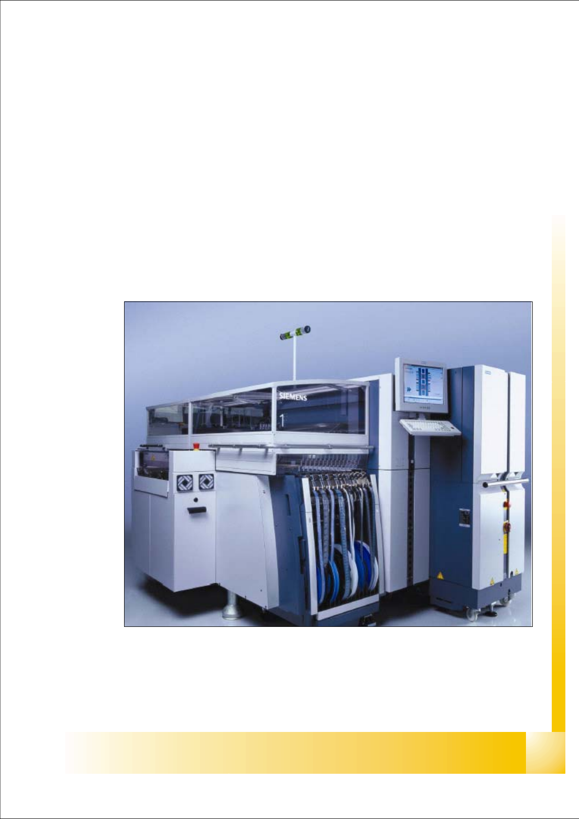
Fig. 11.1 - 1 Siplace machine with MTC 2 at location 2
1 - 2
Student Guide SIPLACE HF/HF3
11 MTC 2 Edition 09/2005
2
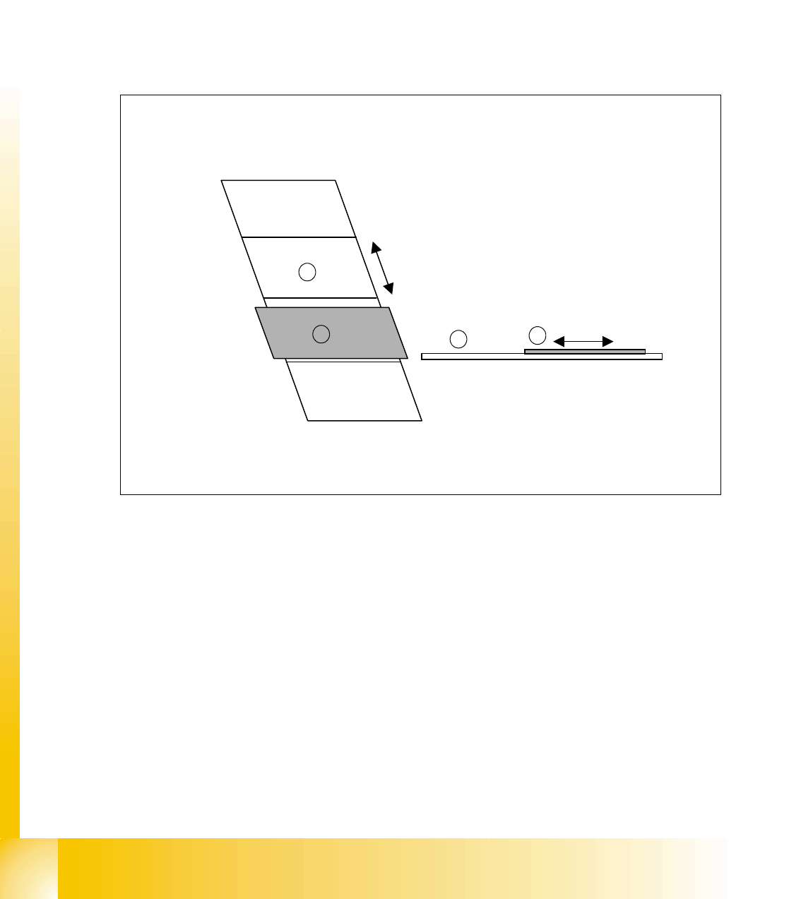
11.1.2 Functional principles
The MTC 2 has two towers which work independently of each other. They each have a lifting axis
and a feed axis. The lifting axes can be set up with a large number of waffle pack trays in cassettes
and transport these vertically. The feed axes transport waffle pack trays which have been set up
horizontally to the pick-up position of the SIPLACE station.
The waffle pack trays (WPT) to be set up are placed in waffle pack tray carriers (WTC). They are
then inserted in a cassette one above the other with a small gap between each of them, and fixed
in place with the WTC interlock. The cassettes are fixed in place in the tower with the cassette
interlock.
Fig. 11.1 - 2 Functional principles of the MTC 2
Key
1. Lifting axis
2. Cassette with WTCs
3. Feed axis
4. WTC on the feed axis
1
2
3
4

1 - 3
Student Guide SIPLACE HF/HF3
Edition 09/2005 11 MTC 2
3
The lifting axes are moved vertically on linear carriages which are driven by a servo motor with a
spindle. The gradient of 20 degrees from the vertical axis reduces the travel path of the WTCs to
the pick-up position of the SIPLACE station.
The WTCs are also moved horizontally on linear carriages which are driven by a servo motor with
a belt drive. A driver locks into the side of the WTC and moves it out of the cassette into the pick-
up position. After the SIPLACE station has picked up the necessary components out of the waffle
pack tray, the WTC is moved back into the cassette again.
The WTCs are transferred between the lifting axis and the feed axis via defined transfer and re-
moval positions. Safety queries from the software ensure that the cassettes and WTCs are always
in the correct location when the lifting axis and feed axis are moved.
Both towers can be set up independently of each other. While one tower is being refilled, the sec-
ond can continue to supply the SIPLACE station with components. This prevents interruptions to
the placement process. Special waffle pack trays are an exception here, since they can only be
set up in one of the towers.
The MTC 2 can be docked to the SIPLACE station instead of a component cart. A separate dock-
ing frame accepts the MTC 2 and fixes it in place with two alignment pins. The exact position is
measured by two camera fiducials during the SIPLACE station reference run. The MTC 2 can be
moved on its own wheels when it is exchanged.
The system is adapted to the different standard heights (Europa and SMEMA) during the initial
setup phase, but can still be changed later without additional tools being required. The height is
adjusted with a crank mechanism when the machine is docked onto the SIPLACE station.