SG_FSE_SiplaceHF_HF3_00193901-05_eng.pdf - 第491页
1 - 17 S tudent Guide SIPLACE HF/HF3 Edition 09/2005 1 1 MTC 2 17 1 1.2 Construction and mode of operation The MTC 2 extends the cap a city of a SIPLACE st ation to supply component s by up to 100 JEDEC waffle pack trays…
1 - 16
Student Guide SIPLACE HF/HF3
11 MTC 2 Edition 09/2005
16
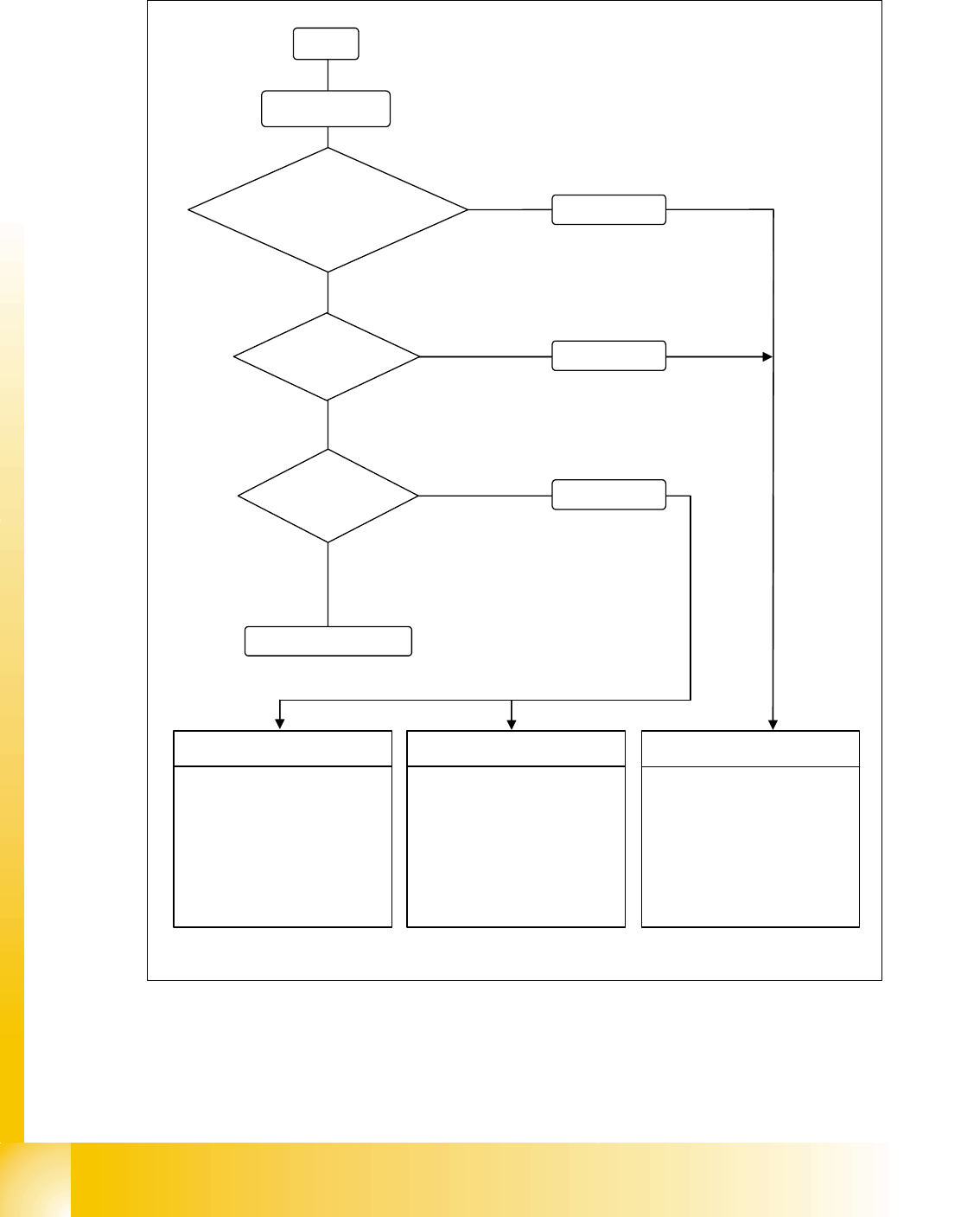
11.1.6.6 Safety loops
Fig. 11.1 - 22 Safety loops
Start
Initialize
Safety loop to
SIPLACE interrupted
Yes
No
No
No
Emergency stop
button pressed
Yes
Yes
Error message
Error message
Protective door
open
Machine inizialized
Tower 1
SSK *) tower 1: not active
SSK *) tower 2: active
Lifting axis 1: 0 V
Feed axis 1: 0 V
Lifting axis 2: 400 V
Feed axis 2: 400 V
Tower 2
SSK *) tower 1: active
SSK *) tower 2: not active
Lifting axis 1: 400 V
Feed axis 1: 400 V
Lifting axis 2: 0 V
Feed axis 2: 0 V
Tower1 andtower2
SSK 1*) tower: not active
SSK 2*) tower: not active
Lifting axis 1: 0 V
Feed axis 1: 0 V
Lifting axis 2: 0 V
Feed axis 2: 0 V
*) CSC Contactor safety combination
Error message

1 - 17
Student Guide SIPLACE HF/HF3
Edition 09/2005 11 MTC 2
17
11.2 Construction and mode of operation
The MTC 2 extends the capacity of a SIPLACE station to supply components by up to 100 JEDEC
waffle pack trays. It has its own controller (C167 controller board) and is integrated into the station
computer software. The setup of the MTC 2 is integrated into the line controller software of a sys-
tem.
Each of the two towers of the MTC 2 comprise a lifting axis and a feed axis. The lifting axes can
be set up with a large number of waffle pack trays in cassettes and transport these vertically. The
feed axes transport waffle pack trays which have been set up horizontally to the transfer position
to the SIPLACE station.
All drive units comprise Masterdrive drive systems:
The servo motors of the lifting axes each drive a spindle via a dual toothed belt, which trans-
ports vertically the cassettes which have been set up. A holding brake in the motors, which is
controlled by the Masterdrive via optocouplers, prevents the axis from moving when the ma-
chine is switched off. The lifting axes remain under control when a position has been reached.
The toothed belts are duplicated for safety reasons and are monitored using inductive sensors.
11
11
The servo motors of the feed axes use a toothed belt and belt gear to move a driver, which
then moves the selected WTC horizontally to the transfer position of the SIPLACE station.
11
11
Lifting axis
One revolution of the servo motor is equivalent to 4096 pulses or a lift of 10 mm on the spindle.
Feed axis
One revolution on the servo motor is equivalent to 4096 pulses or 27.78 mm on the linear guide.
1 - 18
Student Guide SIPLACE HF/HF3
11 MTC 2 Edition 09/2005
18
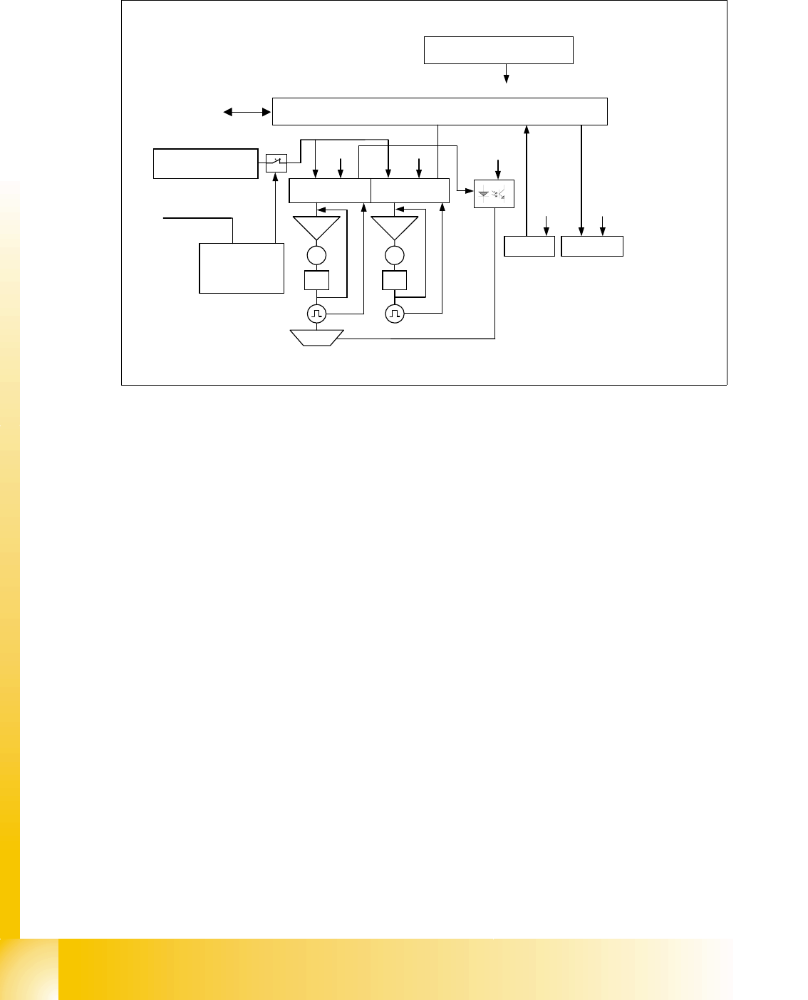
11.2.1 Incorporating the MTC in the SIPLACE station
Fig. 11.2 - 1 The interfaces and power supply of the MTC 2 (shown for tower 1)
11.2.1.1 CAN bus
This interface is used for all commands which are sent by the machine controller of the SIPLACE
station. Example: Reference position run and transfer of set-up data.
11.2.1.2 400 V power supply
The MTC 2 is supplied externally with 400 V (USA/Japan: 208/204 V).
11.2.1.3 EMERGENCY STOP interface
The MTC 2 is incorporated in the safety circuit of the SIPLACE station. This provides feedback in
the form of a protective circuit voltage of 24 V. This protective circuit voltage switches the relevant
combination circuit breaker and thus the 400 V of the inverters for the Masterdrives.
The contactors switch off the servo voltage (400 V) and also immediately switch off the power sup-
ply to the brake.
The signaling contact (make contact) of the EMERGENCY STOP button is connected to the input
of the SIPLACE safety signalling system. The break contact interrupts the 24 V protective circuit
voltage of the SIPLACE machine.
If the EMERGENCY STOP circuit in a machine is interrupted (EMERGENCY STOP button), the
Masterdrives of the MTC 2 trip. Both systems are then not under power.
When one of the two protective doors of the MTC 2 is opened, only the control voltage of the rel-
evant tower falls.
24 V supply voltage
C167 Controller board
Servo
M
PI
Servo
M
PI
Brake
CAN bus
Sensors
CAN Bus
Safety
interface
400 V supply
voltage
SIPLACE
Actuators
24 V
24 V
24 V
24 V 24 V
Masterdrive
lifting axis 1
Masterdrive
feed axis 1
Safety
circuit
1
2
3
4