SG_FSE_SiplaceHF_HF3_00193901-05_eng.pdf - 第495页
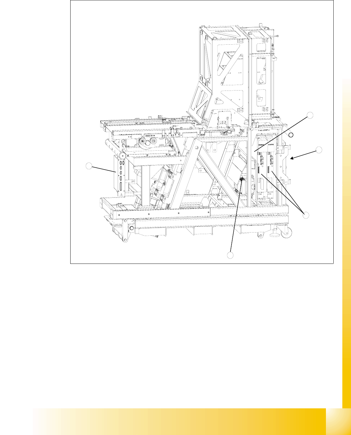
1 - 21 S tudent Guide SIPLACE HF/HF3 Edition 09/2005 1 1 MTC 2 21 1 1.2.4 Modules of the controller Fig. 1 1.2 - 2 Modules of the controller Key 2. C167 controller board 3. Masterdrives (shown for tower 1) 4. 24V power s…

1 - 20
Student Guide SIPLACE HF/HF3
11 MTC 2 Edition 09/2005
20
11.2.3 Installation MTC 2
The MTC 2 can only be run in conjunction with a SIPLACE station and not as an independent ma-
chine. The settings (machine data) are saved in the battery backed memory of the machine con-
troller and are only valid for this particular machine.
When the MTC 2 has been delivered, the following steps must be performed before the first time
the machine is used:
➠ Check the basic height and if necessary set it (see the User Manual).
➠ Check that the power supply has been set correctly (see Chapter 13.3.14 or Adjustment In-
struction).
➠ Check that all axes can move freely.
➠ Check the toothed belt for correct tension and damage: (seeAdjustment Instruction)
If there is evidence of damage to the toothed belt, it must be replaced (see the Service Instruc-
tions).
➠ Prepare the SIPLACE station (see Chapter 13.2.6).
➠ Dock the MTC 2 to the SIPLACE station (see the User Manual).
➠ Switch on the SIPLACE station and the MTC 2.
➠ Log on to the station computer software at the Service access level.
➠ Start SITEST.
➠ In the basic view, switch to the menu for the MTC 2.
➠ Perform a reference run on the MTC 2.
➠ Perform a reference run on the SIPLACE station.
➠ Perform a functional test on the safety equipment by carrying out each of the following actions
individually during subsequent reference runs:
➠ Press the EMERGENCY STOP button.
➠ Open the protective doors.
➠ Leave the tower locking mechanism open before the reference run.
There must be an EMERGENCY STOP and a corresponding error message must be output
on the screen.
11
➠ Undo the relevant action and confirm the error message.

1 - 22
Student Guide SIPLACE HF/HF3
11 MTC 2 Edition 09/2005
22
11.2.4.1 C167 controller board
The controller program (firmware) on the C167 controller board is saved in a flash EPROM. The
version number can be queried from the SITEST program.
The machine data and the set-up are saved in RAM. After the machine is switched off, the data is
held by a buffer battery (buffer time approx. 3.5 years), which is also located on the C167 controller
board. In addition, an electrolytic capacitor ("Goldcap") with a capacity of 1 F is fitted. This saves
the data for approximately 8 hours when the buffer battery is changed.
The "neutral position" light barriers and the software limit switches are wired to the Masterdrives
and are made available there via the CAN bus of the controller.
Tasks:
– Communicating with the station computer of the SIPLACE station
– Controlling the machine via the firmware
– Exchanging data with the axis controllers
– Saving the firmware (flash EPROM)
– Saving the machine data and the set-up (battery-buffered RAM)
– Saving machine-specific parameters, such as serial numbers (in the EEPROM)
– Providing a realtime clock
– Inputs for sensors
– Displaying operating statuses and error statuses via LEDs
Two RS232 interfaces (maximum transfer rate: 115.2 kBaud/s)
COM 1: Test interface for debugging service
COM 2: Free
Two CAN bus interfaces (maximum transfer rate: 1 MBaud/s)
CAN1: Communication with the SIPLACE station
CAN2: Control of the 4 Masterdrives
Power supply:24 V DC
Power consumption:500 mA
24 inputs via a 37-pole Sub-D connector for the sensors
8 inputs via a 15-pole Sub-D connector for the actuators;
The outputs are short-circuit proof;
11
Current per output: 0.7 A, briefly up to 2.5A 11