SG_FSE_SiplaceHF_HF3_00193901-05_eng.pdf - 第498页
1 - 24 S tudent Guide SIPLACE HF/HF3 1 1 MTC 2 Edition 09/2005 24 1 1.2.4.5 Mounting plate A mounting p late with t he following comp onents: – Combination circuit breakers: K03 - K05 – Braking resistor: R01 – Braking re…

1 - 23
Student Guide SIPLACE HF/HF3
Edition 09/2005 11 MTC 2
23
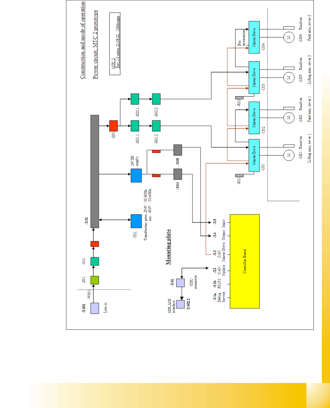
11.2.4.2 Masterdrives
The Masterdrives are controlled via the internal CAN bus system between microcontroller and
masterdrive.
– Controlling the holding brakes for the lifting axes
– Controlling the braking resistors of the lifting axes
– Controlling the permanently excited synchronous motors of the lifting and feed axes
– Evaluating the resolver
11.2.4.3 24V power supply
The 24V power supply supplies:
– The C167 controller board
– The logic circuitry of the Masterdrives
– The sensors and the actuators
11.2.4.4 Electronics board
Electronics board with the following components:
– Main switch:S01
– EMERGENCY STOP button:S15
– Automatic circuit breakers:F00 main fuse
F01 24V sensors 1
11
F02 24V sensors 2, Masterdrive control voltage 11
– Motor protection swtich:Q01 Masterdrives
– Contactors: K01.1 Masterdrive lifting axis tower 1
K01.2 Masterdrive feed axis tower 1
11
K02.1 Masterdrive lifting axis tower 2 11
K02.2 Masterdrive feed axis tower 2 11
– Optocouplers:U09 brake tower 1
U06 brake tower 2
11
– Terminal strips:
X01 supply
X02 24V power supply sensors / actuators
11
X03 EMERGENCY STOP circuit 11
X04 sensors / actuators tower 1 11
X05 sensors / actuators tower 2 11
X06 sensors / actuators 11
1 - 24
Student Guide SIPLACE HF/HF3
11 MTC 2 Edition 09/2005
24
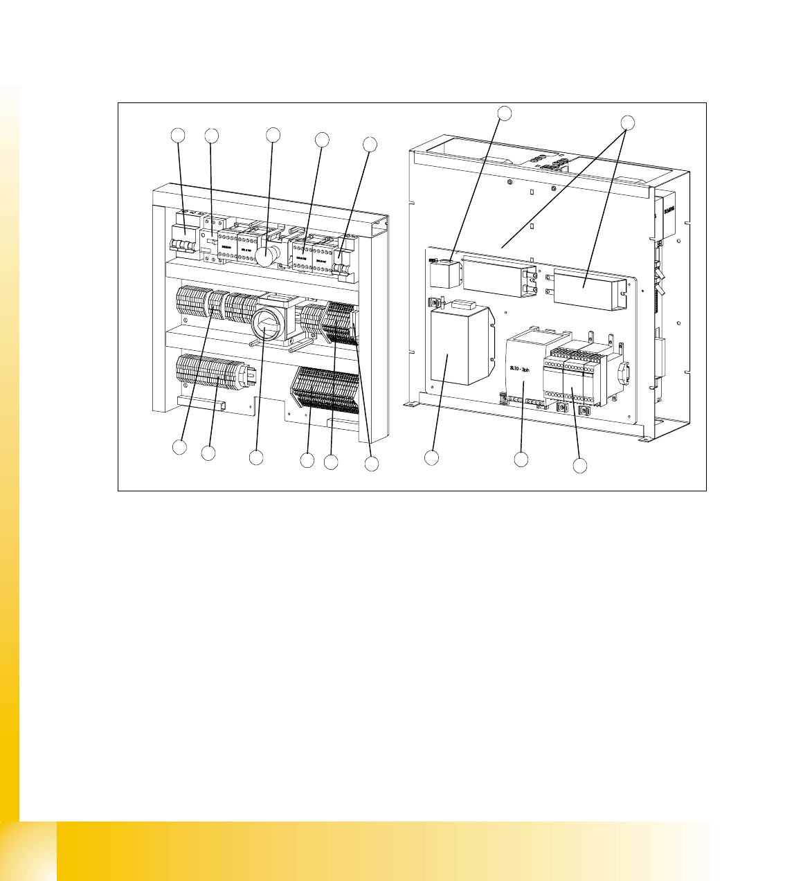
11.2.4.5 Mounting plate
A mounting plate with the following components:
– Combination circuit breakers: K03 - K05
– Braking resistor: R01
– Braking resistor: R02
– Power supply, 24 V DC: T01
– Line filter: Z01
– Discharge reactor (Is this part missing in your MTC please order the retrofitting kit 03016518-
01, that for your own safety.)
Fig. 11.2 - 3 Electronics board and mounting plate
Key
1 Main switches 8 Initiator LED terminals
2 EMERGENCY STOP button 9 Actuator LED terminals
3 Automatic circuit breakers 10 Optocouplers
4 Motor protection switches 11 Combination circuit breakers
5 Contactors 12 Braking resistors
6 Grounding terminals 13 Power supply
7 Through terminals 14 Line filters
15 Discharge reactor
8
3
6
4
2
5
1
9
13
14
11
10
7
3
12
15