SG_FSE_SiplaceHF_HF3_00193901-05_eng.pdf - 第51页
1 - 25 S tudent Guide SIPLACE HF/HF3 Edition 09/2005 2 Overview 25 2.2.10 Construc tion X-Axis 2 Fig. 2.2 - 15 Structure X-Axis The X-Axis consist of the fo llowing main modules: The gantry arm is identical on the origin…
1 - 24
Student Guide SIPLACE HF/HF3
2 Overview Edition 09/2005
24
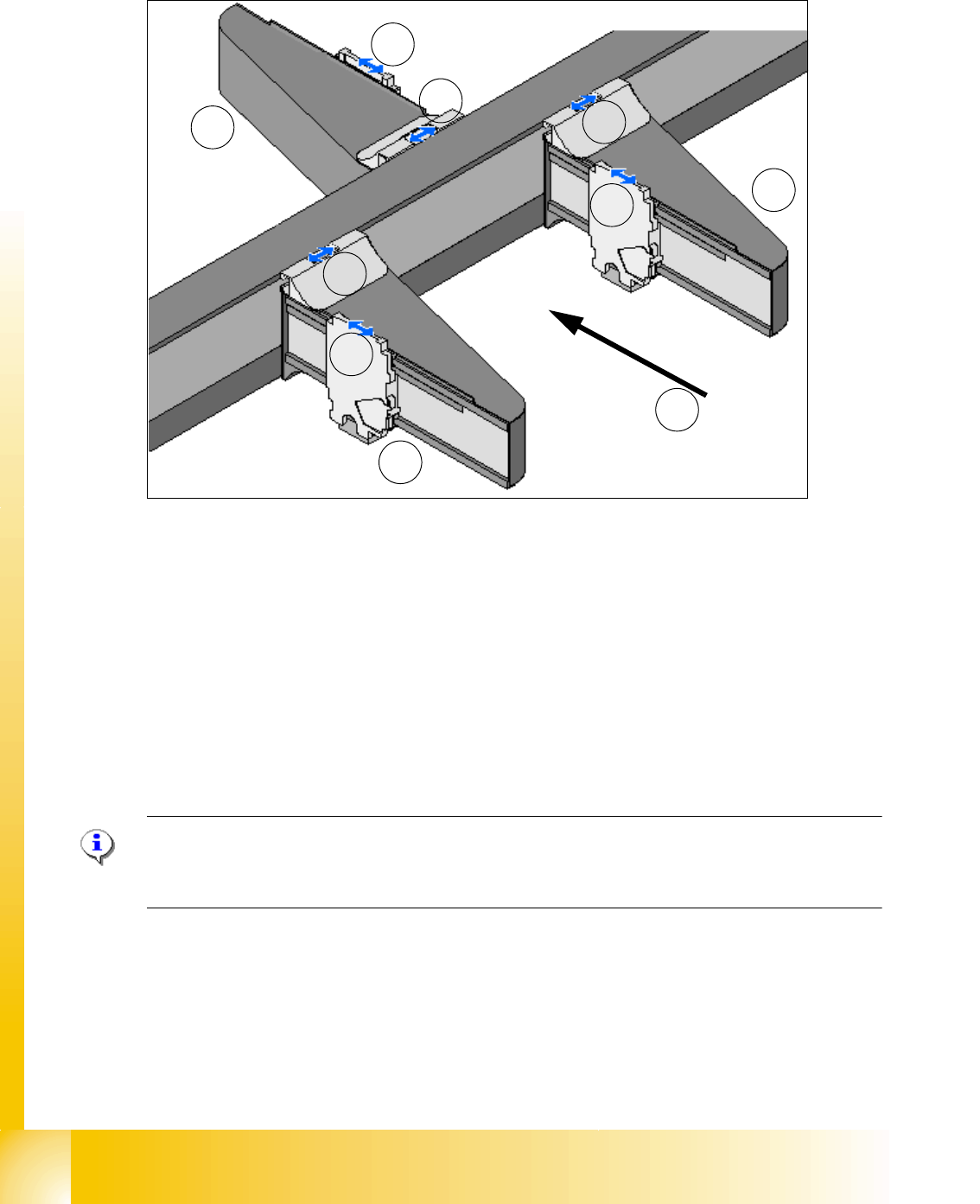
2.2.9 Position of the gantrys
Fig. 2.2 - 14 Position of the gantries HF3
Legend:
Please Note
The HF machine have only two gantries. The name of this Gantries with Stationsoftware
505.xx is Gantry 1 and Gantry 3.
G1Gantry 1 G3Gantry 3
X1X-Axis, Gantry 1 X3X-Axis, Gantry 3
Y1Y-Axis, Gantry 1 Y3Y-Axis, Gantry 3
G4Gantry 4
X4X-Axis, Gantry 4 (T)Transport direction
Y4Y-Axis, Gantry 4
G4
G1
G3
Y4
Y3
Y1
X4
X3
X1
T
1 - 25
Student Guide SIPLACE HF/HF3
Edition 09/2005 2 Overview
25
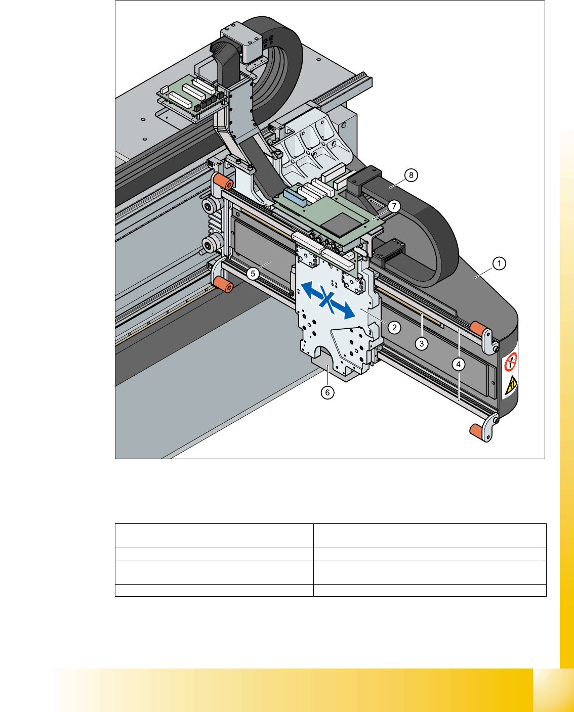
2.2.10 Construction X-Axis
2
Fig. 2.2 - 15 Structure X-Axis
The X-Axis consist of the following main modules:
The gantry arm is identical on the original- and on the ’A’ machine version.
(1) Gantry X (Frame) (2)Mounting plate head with X-linear motor (pri-
mary part)
(3) Linear incremental encoder (4) Linear guides X-Axis
(5)Linear drive Permanent magnet (sec-
ondary part)
(6) PCB-camera
(7) head interface board (8)trailing cable X-Axis

1 - 26
Student Guide SIPLACE HF/HF3
2 Overview Edition 09/2005
26
On the head mounting plate (2) are the following modules mounted:
– PCB camera (6)
– Head boards (7) (head interface, head adapter)
– Incremental encoder
– Collect&Place-head or SIPLACE Twin Head
The gantry arm (Pos. 1 in fig. 2.2 - 15
) is produced of carbon fiber material. This technology given
the gantry arm extreme stiffness with lowest weight. The X axis is driven by a linear motor. The
second part of the drive consists of a permanent magnet and is mounted at the gantry arm, the
primary part is screwed to the head holder.The head holder was constructed that it can mounted
all head types - a further feature for the great flexibility which is achieved with SIPLACE automats.
2.2.10.1 Technical data X-Axis
2
Drive direct, Linear drive
Max. velocity 2,5 m/sec
Travel range 471 mm
Travel range mechanical 480 mm
Measurement system Linear incremental encoder
Lenght of linear incremental encoder 520 mm
Resolution 1 µm