SG_FSE_SiplaceHF_HF3_00193901-05_eng.pdf - 第514页
1 - 40 S tudent Guide SIPLACE HF/HF3 1 1 MTC 2 Edition 09/2005 40 Fig. 1 1.3 - 4 Maximum position ➠ Now calculate the middle position at which the driver will always engage. e.g. |-257| + 596 = 85 3 divided 2 = 426µm 426…
1 - 39
Student Guide SIPLACE HF/HF3
Edition 09/2005 11 MTC 2
39
11.3.2.2 Feed axes
Notes for calibration the zeropoint correction and transfer position into the machine. 11
1a. Calibration of zero point correction: 11
➠ Carry out the relevant preparatory measures (see section 5.2.2 "Preparatory measures").
➠ Select SITEST --> MTC --> Settings
➠ Press the button "Teach zero point"
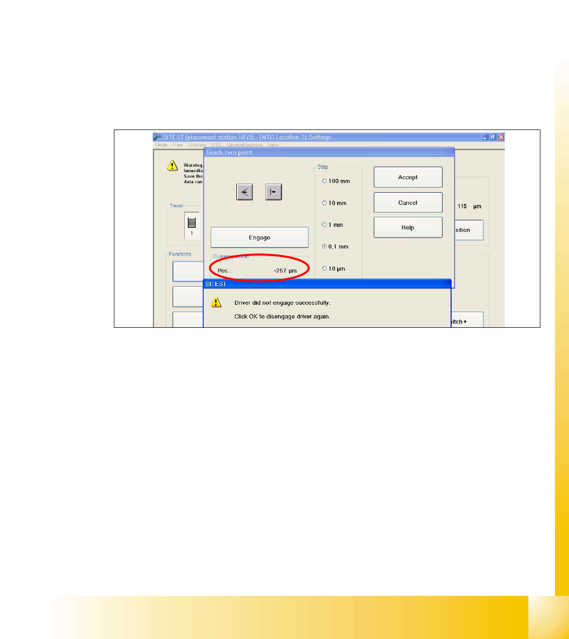
➠ Check the position of the driver with the button "ENGAGE". In case the driver did not engaged
successfully you must determine the middle of the notch of the waffel pack tray.
The accurate adjustment is described below:
➠ Determine the minimum position of the notch Fig. 11.3 - 3.
Fig. 11.3 - 3 Minimum position
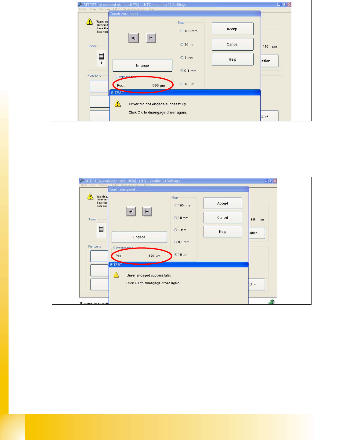
➠ Determine the maximum position of the notch Fig. 11.3 - 4. at which the driver just engages no
more.
1 - 40
Student Guide SIPLACE HF/HF3
11 MTC 2 Edition 09/2005
40
Fig. 11.3 - 4 Maximum position
➠ Now calculate the middle position at which the driver will always engage.
e.g. |-257| + 596 = 853 divided 2 = 426µm
426 + the minimum pos. or maximum pos. - 426 = approx.169µm
Fig. 11.3 - 5 Correct position for the driver
➠ Check the driver position. The driver now should be correctly in the middle position of the notch
of the WTC.
➠ Press the button "ACCEPT"
➠ Check the position of the driver for the other cassettes.
1 - 41
Student Guide SIPLACE HF/HF3
Edition 09/2005 11 MTC 2
41
1b. Manuall Input of the Zero point correction 11
After the calibration of the zeropoint correction , the value will put in the row " removal position
Cassette 1" from the machine data.
Is this value to big, it is not possible to calibrate the max. and min. travel range of the feed axis.
Reason: The travel range will be calculate from the row "Zero point correction". When you have
the value zero in the row zero point correction, the feed axis move against the limit switch during
the calibration procedure.
Solution:
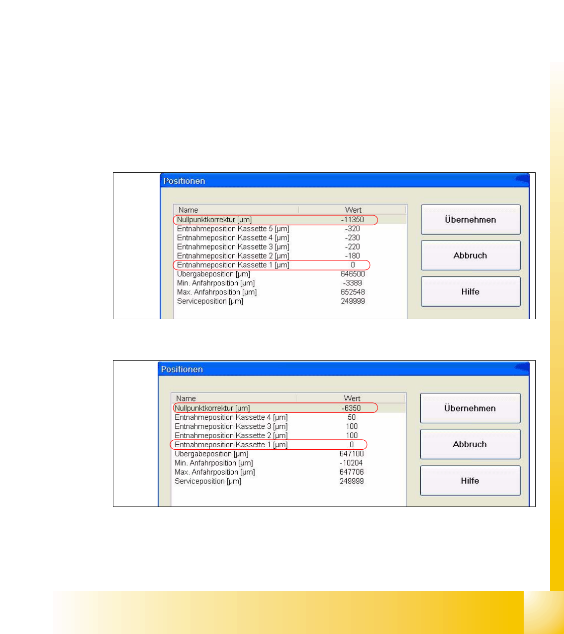
Put in the calibrated value in the row "Zero point correction" and the value zero in the row " Position
of removal Position cassette 1".
Sitest:
–MTC -->Axes
– Choose feed axis
– Press the button "Positions"
Fig. 11.3 - 6 Example: Input machine data tower 1
Fig. 11.3 - 7 Example: Input machine data tower 2
After the manuall Inputs, check the Zero point correction again.