SG_FSE_SiplaceHF_HF3_00193901-05_eng.pdf - 第521页
1 - 47 S tudent Guide SIPLACE HF/HF3 Edition 09/2005 1 1 MTC 2 47 1 1.3.3 Adjustment s Lif ting Axes Fig. 1 1.3 - 13 Overview of the lifting axes Key 1 L ifting axis tower 1 2 L ifting axis tower 2 3 Serv o motors of the…
1 - 46
Student Guide SIPLACE HF/HF3
11 MTC 2 Edition 09/2005
46
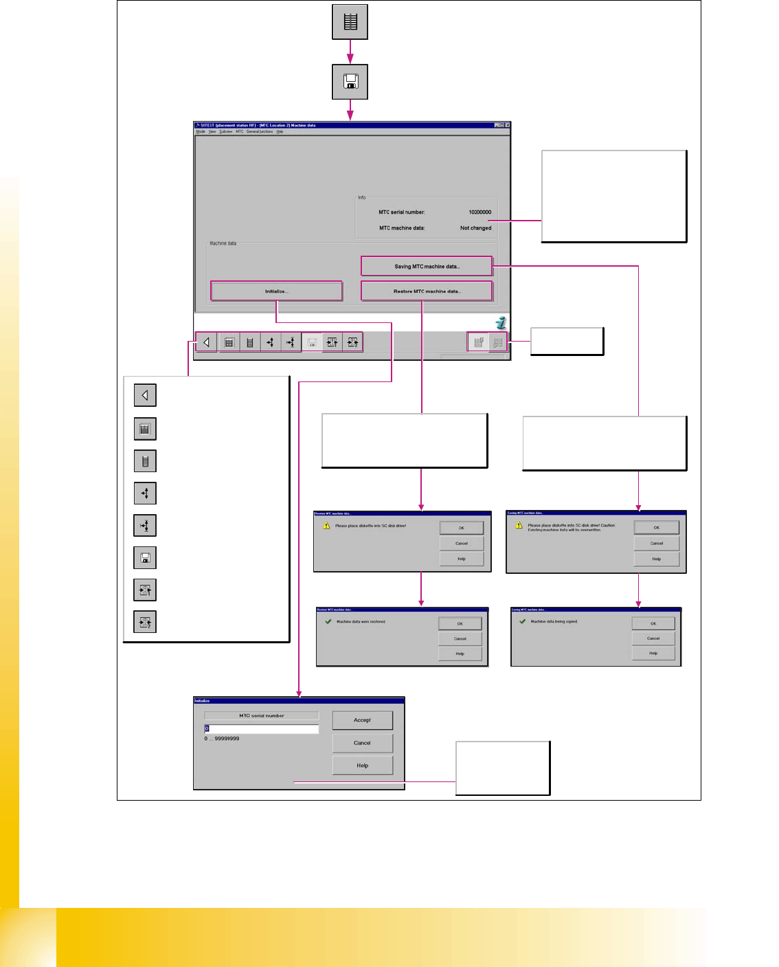
11.3.2.3 Machine data MTC
Fig. 11.3 - 12 Storage machine data
Save Machine-Data: With the SW 601, it is not possible to save the data onto the floppy disc.
Now you can choose a folder and save the mtc.ma (e.g. Memory Stick)
Calls the view for the functions
of the MTC.
Calls the view for the tower
functions of the MTC.
Calls the view for the axis
functions of the MTC.
Calls the view for the settings of
the MTC.
Calls the view for the machine
data functions of the MTC.
Calls the view for the inputs/
outputs of the MTC.
Calls the view for the inputs/
outputs of the MTC.
Return to the main view.
Selects the MTC
at location 2 or 4.
The file mtc.ma, which contains the machine
data for the MTC, is copied from floppy disk
to the directory C:\SRDaten\srcma of the
station computer. The machine data is then
transferred to the MTC.
This saves the changes to the machine data
of the MTC in a file called mtc.ma which is
located in the directory C:\SRDaten\srcma
of the station computer. The file mtc.ma is
subsequently copied to floppy disk.
MTC serial number
Enter the serial number
of the MTC here.
The serial number can
be found on the MTC.
Info
MTC serial number
The serial number of the MTC is
displayed here.
MTC machine data
The current status of the MTC
machine data is shown here, the value
may be "Changed" or "Not changed".
1 - 47
Student Guide SIPLACE HF/HF3
Edition 09/2005 11 MTC 2
47
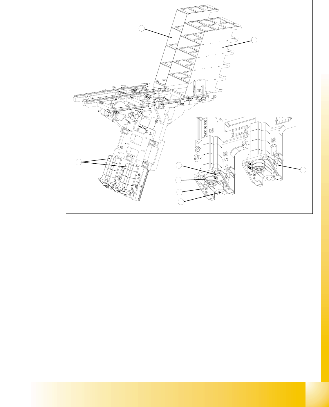
11.3.3 Adjustments Lifting Axes
Fig. 11.3 - 13 Overview of the lifting axes
Key
1 Lifting axis tower 1
2 Lifting axis tower 2
3 Servo motors of the lifting axes
4 Dual toothed belt (shown here for tower 2)
5 Spindle (shown here for tower 2)
6 Inductive sensors (shown here for tower 2)
7 Holes for the measurement head of the belt frequency measuring device
3
2
6
4
5
1
7
7
1 - 48
Student Guide SIPLACE HF/HF3
11 MTC 2 Edition 09/2005
48
11.3.3.1 Belt tension
Note:
The construction of the lifting axis was change since 05.2005. That means new spindle, spindle
with counter bearing, motor lifting axis, gear on the motor and therefore new parametersets for
Masterdrives. The MTC 2 has the versionsnumber 02. The belt tension for the lifting axis was
change, please note!
Tools and accessories 11
– Belt frequency measurement device (inductive)
– 2 belt tension stickers
– 1 set of hexagon socket wrenches
– 1 set of open-ended wrenches
Preparatory measures 11
➠ Empty the MTC 2 completely (see the User Manual).
➠ Move the lifting axis to its lowest position (see Sitest ).
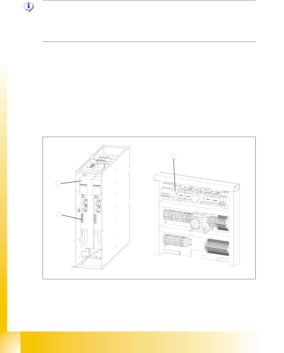
Fig. 11.3 - 14 Connections to the Masterdrives of the lifting axes
Key
1 Masterdrive, lifting axis (shown here for tower 1)
2 Connection terminal for external signals
3 Motor protection switch on the electronics board
2
1
3