SG_FSE_SiplaceHF_HF3_00193901-05_eng.pdf - 第527页
1 - 53 S tudent Guide SIPLACE HF/HF3 Edition 09/2005 1 1 MTC 2 53 Fig. 1 1.3 - 17 Guide r ails, bottom Key 1 G uide rails 2 Attachment screws 1 1.3.3.3 Cassette guide rails T ools and accessories 11 – 1 set of hexa gon s…

1 - 52
Student Guide SIPLACE HF/HF3
11 MTC 2 Edition 09/2005
52
Checking and setting the guide rails, top 11
➠ Manually open the WTC interlock for each WTC which has been set up and check that the
WTC can be pulled out approx. 0.5 to 1mm up to the closed guide rail. When closing the WTC
interlock, the WTC must automatically click into place.
➠ Open the guide rail. When closing the guide rail, use a WTC which has been pulled out to
check either:
– that the WTC engages in the WTC interlock again on its own or
– that the guide rail cannot be closed.
➠ Set the position of the guide rail (by moving it in its fixing holes), if the behavior described above
is not observed.
Checking and setting the stopper bars, top 11
➠ Manually open the side interlock (leaf springs) for each WTC and check that the WTC can be
pushed through approx. 0.5 to 1mm up to the stopper bar. When closing the interlock, the WTC
must click into place automatically.
➠ Set the position of the stopper bar (by moving it in its fixing holes), if the behavior described
above is not observed. If necessary, remove the covers behind the doors.
Check on tower 1 that a WTC XL with 25 mm-high components can be transported without
colliding with the stopper bar. If necessary, correct the position of the stopper bar.
Checking and setting the stopper bars, bottom 11
➠ Move the doors fully down
➠ Remove the side covers
➠ Set the position of the guide rails until they are approx. 0.5 through 1mm away from the WTCs.
WARNING
The stopper bar and guide rail must under no circumstances touch the WTCs!
1 - 53
Student Guide SIPLACE HF/HF3
Edition 09/2005 11 MTC 2
53
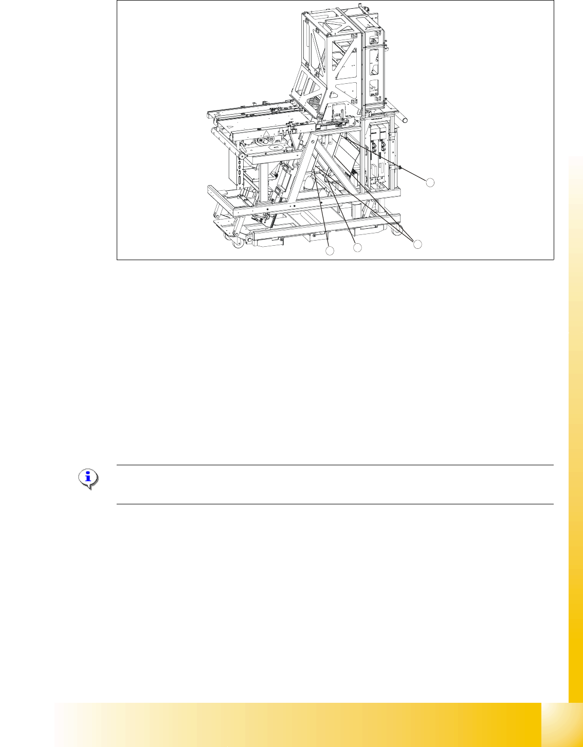
Fig. 11.3 - 17 Guide rails, bottom
Key
1 Guide rails
2 Attachment screws
11.3.3.3 Cassette guide rails
Tools and accessories 11
– 1 set of hexagon socket wrenches
Preparatory measures 11
NOTE
An empty cassette is needed to set the cassette guide rails.
➠ Empty the MTC 2 completely (see the User Manual).
➠ Prepare an empty cassette XL.
Setting the cassette guide rails 11
1
2
2
2
1 - 54
Student Guide SIPLACE HF/HF3
11 MTC 2 Edition 09/2005
54
11
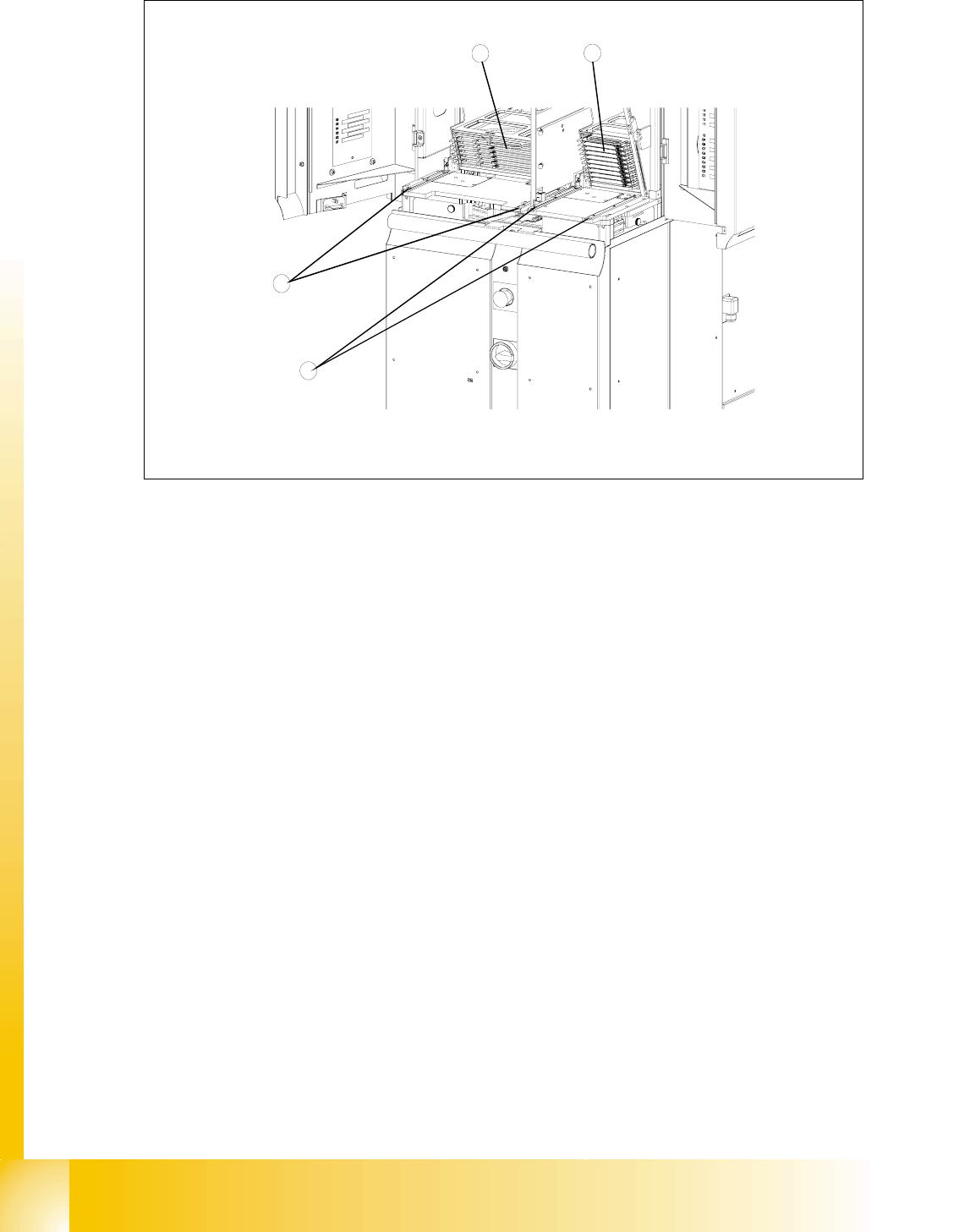
Fig. 11.3 - 18 Setting the cassette guide rails
Key
1 Cassette XL in the refill position for tower 1
2 Cassette in the refill position for tower 2
3 Cassette guide rails for tower 1
4 Cassette guide rails for tower 2
➠ Move the lifting axis into the refill position for cassette 1
➠ Loosen the securing screws on both cassette guide rails.
➠ Tighten the securing screws of the inner cassette guide rail at the position in which the cassette
can still be inserted into the tower smoothly.
➠ Position the second cassette guide rail by means of the cassette parallel to the first cassette,
so that the cassette can be moved easily but without any lateral play. Tighten the securing
screws here as well.
➠ Check the setting of the other refill positions.
➠ If necessary, correct the position of the cassette guide rails which has been set.
4
3
1
2