SG_FSE_SiplaceHF_HF3_00193901-05_eng.pdf - 第529页
1 - 55 S tudent Guide SIPLACE HF/HF3 Edition 09/2005 1 1 MTC 2 55 1 1.3.4 Adjustment s feed axes Fig. 1 1.3 - 19 Overview of the feed axes (cover plates and belt covers removed) Key 1 Feed axis, tower 1 2 Feed axis, towe…
1 - 54
Student Guide SIPLACE HF/HF3
11 MTC 2 Edition 09/2005
54
11
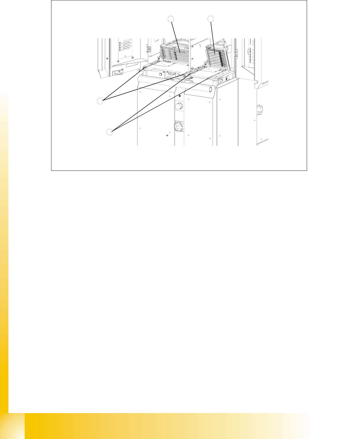
Fig. 11.3 - 18 Setting the cassette guide rails
Key
1 Cassette XL in the refill position for tower 1
2 Cassette in the refill position for tower 2
3 Cassette guide rails for tower 1
4 Cassette guide rails for tower 2
➠ Move the lifting axis into the refill position for cassette 1
➠ Loosen the securing screws on both cassette guide rails.
➠ Tighten the securing screws of the inner cassette guide rail at the position in which the cassette
can still be inserted into the tower smoothly.
➠ Position the second cassette guide rail by means of the cassette parallel to the first cassette,
so that the cassette can be moved easily but without any lateral play. Tighten the securing
screws here as well.
➠ Check the setting of the other refill positions.
➠ If necessary, correct the position of the cassette guide rails which has been set.
4
3
1
2
1 - 55
Student Guide SIPLACE HF/HF3
Edition 09/2005 11 MTC 2
55
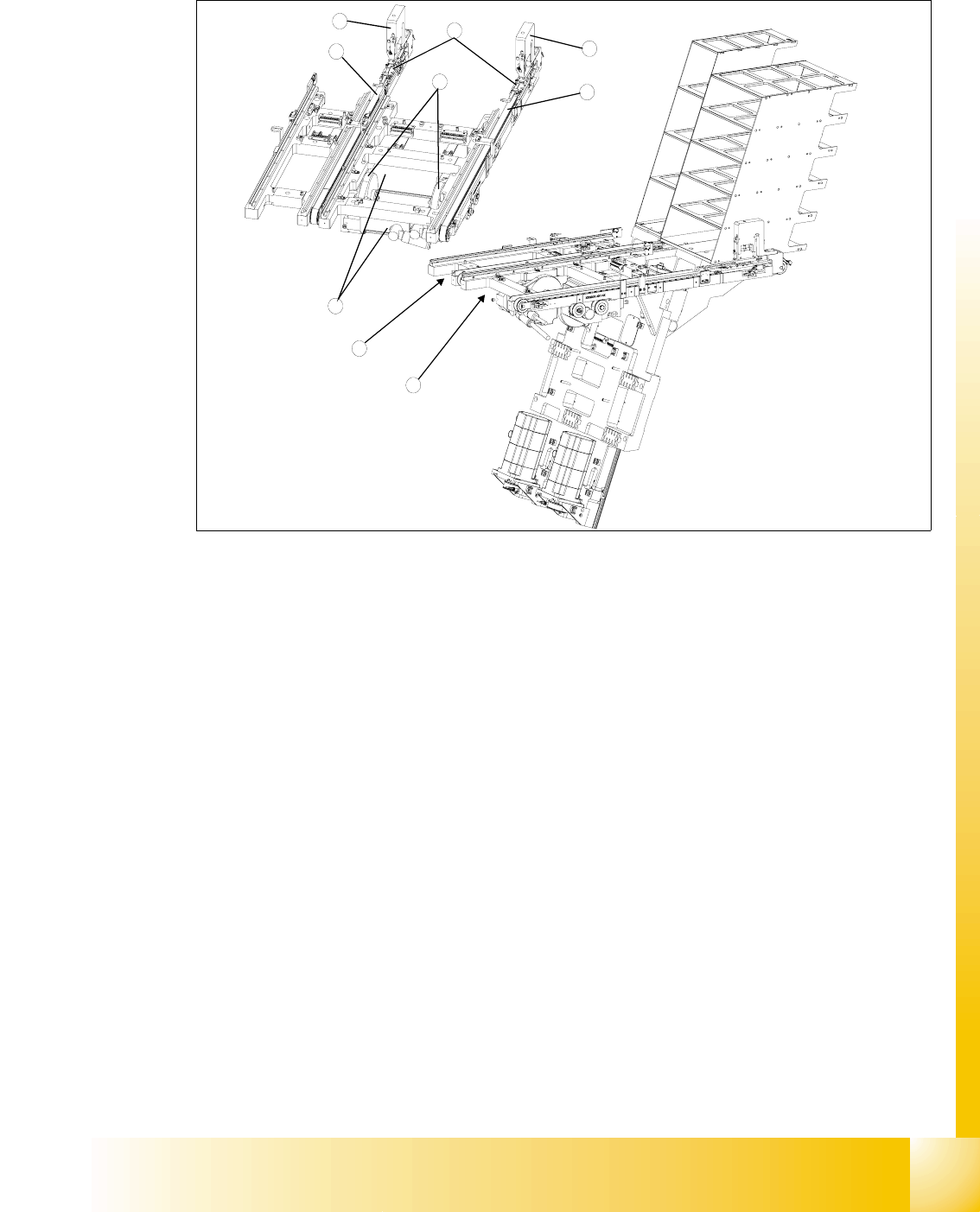
11.3.4 Adjustments feed axes
Fig. 11.3 - 19 Overview of the feed axes (cover plates and belt covers removed)
Key
1 Feed axis, tower 1
2 Feed axis, tower 2
3 Servo motors of the feed axes
4Drive belt
5 Toothed belt
6 Disengaging mechanisms
7Driver
11.3.4.1 Belt tension
Tools and accessories 11
– Belt frequency measurement device (inductive)
– 2 toothed belt tension stickers
– 1 set of hexagon socket wrenches
– 1 set of open-ended wrenches
2
1
3
4
5
6
5
6
7
1 - 56
Student Guide SIPLACE HF/HF3
11 MTC 2 Edition 09/2005
56
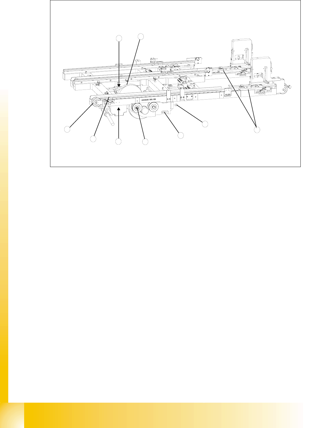
Fig. 11.3 - 20 Checking and setting the belt tension
Key
1 Drive belt (shown here for tower 2)
2 Motor mounting block with clamping screws (shown here for tower 1)
3 Adjustment screw, drive belt (shown here for tower 1)
4 Measuring point, drive belt (shown here for tower 2)
5 Toothed belt (shown here for tower 1)
6 Eccentric axle of toothed belt with clamping screw and flats for setting (shown here for tower 1)
7 Measuring point, toothed belt (shown here for tower 1)
8 Outer deflection roll (shown here for tower 1)
9Driver
Preparatory measures 11
➠ Empty the MTC 2 completely (see the User Manual).
➠ Undock the MTC 2 from the SIPLACE station (see User Manual).
➠ Remove both cover plates between the rails of the feed axes.
Checking and setting the drive belt 11
➠ Carry out the relevant preparatory measures (see section 11.3.4.1 "Preparatory measures").
➠ Measure the belt tension with the belt frequency measuring device in the following way:
➠ Cause the drive belt to oscillate and measure the frequency in the middle of the sloping
surface between the motor axis and the belt wheel (for the measuring point, see
Fig. 11.3 -
2
4
1
6
3
7
5
9
8