SG_FSE_SiplaceHF_HF3_00193901-05_eng.pdf - 第53页
1 - 27 S tudent Guide SIPLACE HF/HF3 Edition 09/2005 2 Overview 27 2.2.1 1 Construction Y - axis 2 Fig. 2.2 - 16 Construction Y -Axis Legend The Y- A x i s consist of the fol lowing main modules: The Y axis is driven by …

1 - 26
Student Guide SIPLACE HF/HF3
2 Overview Edition 09/2005
26
On the head mounting plate (2) are the following modules mounted:
– PCB camera (6)
– Head boards (7) (head interface, head adapter)
– Incremental encoder
– Collect&Place-head or SIPLACE Twin Head
The gantry arm (Pos. 1 in fig. 2.2 - 15
) is produced of carbon fiber material. This technology given
the gantry arm extreme stiffness with lowest weight. The X axis is driven by a linear motor. The
second part of the drive consists of a permanent magnet and is mounted at the gantry arm, the
primary part is screwed to the head holder.The head holder was constructed that it can mounted
all head types - a further feature for the great flexibility which is achieved with SIPLACE automats.
2.2.10.1 Technical data X-Axis
2
Drive direct, Linear drive
Max. velocity 2,5 m/sec
Travel range 471 mm
Travel range mechanical 480 mm
Measurement system Linear incremental encoder
Lenght of linear incremental encoder 520 mm
Resolution 1 µm
1 - 27
Student Guide SIPLACE HF/HF3
Edition 09/2005 2 Overview
27
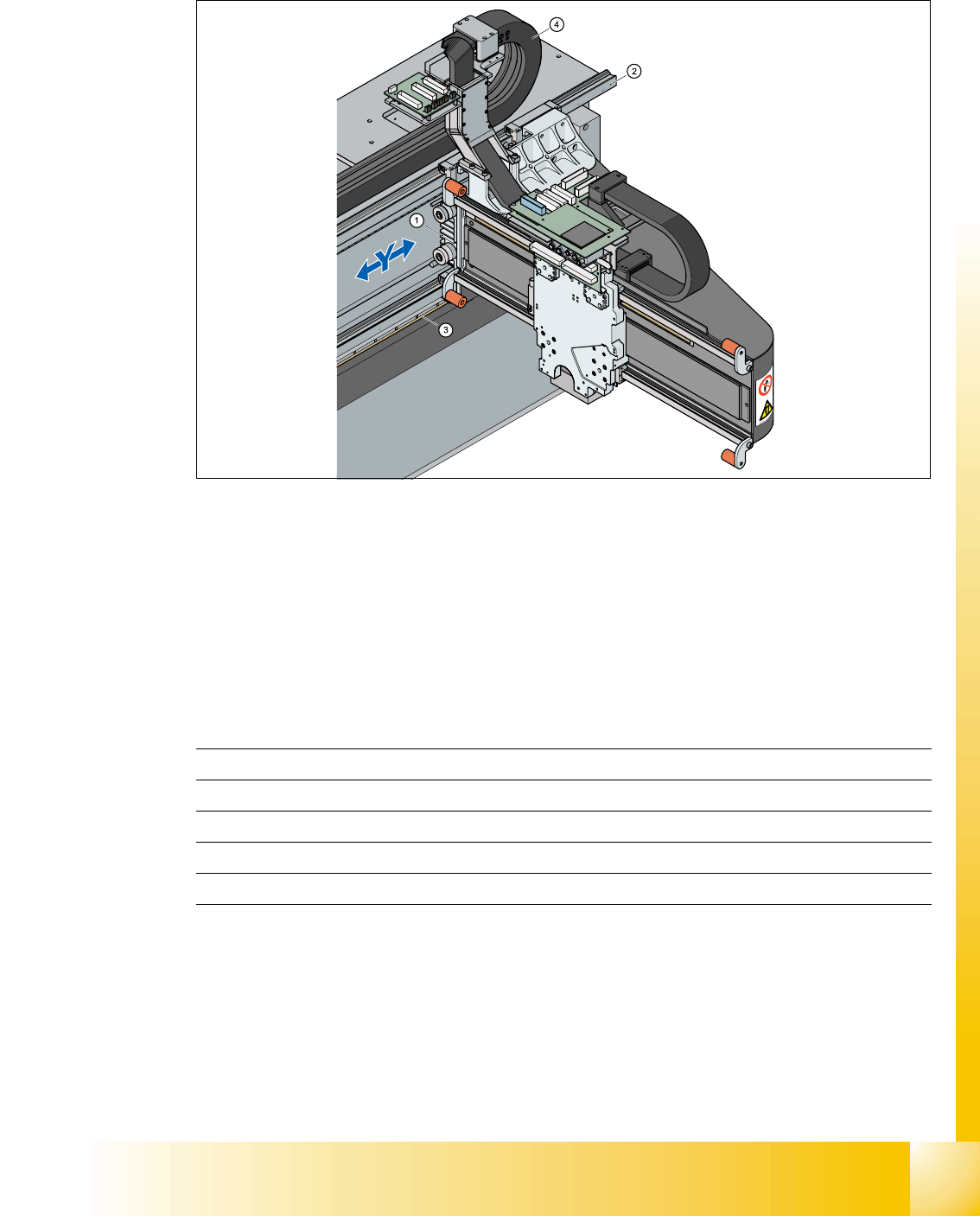
2.2.11 Construction Y-axis
2
Fig. 2.2 - 16 Construction Y-Axis
Legend The Y-Axis consist of the following main modules:
The Y axis is driven by a linear motor. The second part of the drive consists of a permanent mag-
net and is mounted at the machine frame. The primary part is screwed to the gantry arm (X-Axis).
Technical data Y-Axis 2
2.2.12 Cameras
Each 12-segment- and each 6-segment-Collect&Place-head contains your own component cam-
era. The finepitch-visionmodul for the Twin-Head is mounted on the machine frame.
(1) Linear drive Permanent magnet (2) Linear incremental encoder
(3) Linear guide (4) Trailing cable Y-Axis
Drive direct, Linear drive
Max. velocity 2,5 m/sec.
Travel range gantry 1430 mm
Lenght incremental encoder 1850mm
Resolution 1 µm
1 - 28
Student Guide SIPLACE HF/HF3
2 Overview Edition 09/2005
28
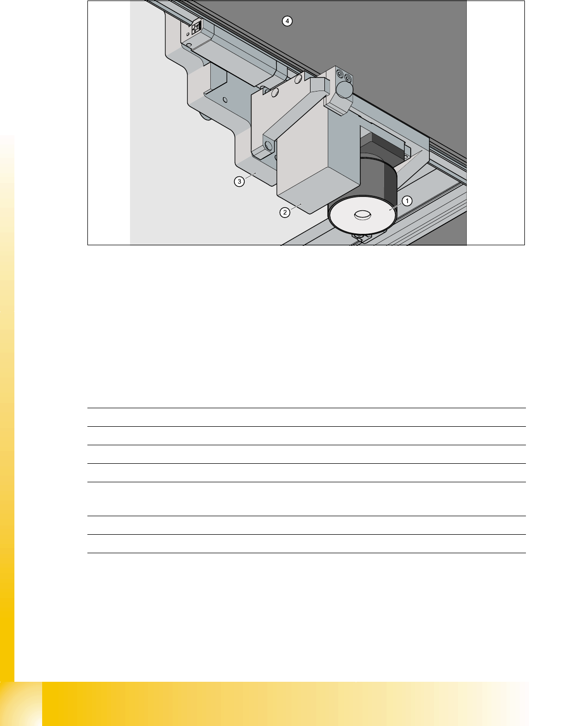
2.2.12.1 Standard modul PCB Camera
2
Fig. 2.2 - 17 PCB camera under the Gantry (X-Axis)
1. PCB-camera - Optics and illumination
2. Camera amplifier
3. Head mounting plate
4. Gantry
5. Damping unit
Technical Data 2
Option: Multicolor camera available (Camera type 18.sst) 2
5
PCB fiducial max. 3 per placement program
memory capacity for fiducial max. 255 PCB-fiducial - System fiducial ≥ 249
Image processing Geometric Alignment
Kind of illumination from above
Time for fiducial recognition per fiducial/
bad fiducial
0,4 s
Field of view 5,7 mm x 5,7 mm
Camera type .sst 5.sst