SG_FSE_SiplaceHF_HF3_00193901-05_eng.pdf - 第532页
1 - 58 S tudent Guide SIPLACE HF/HF3 1 1 MTC 2 Edition 09/2005 58 NOTE: Before the limit switches ar e set, the ze ro of fset and the transfer position m ust be checked. ➠ Check the zero offse t (see section 1 1.3.2.2). …

1 - 57
Student Guide SIPLACE HF/HF3
Edition 09/2005 11 MTC 2
57
20, item 4). You must set the belt tension if the measured frequency deviation deviates from
the nominal value
(120 Hz ± 5 Hz):
➠ Turn the adjusting screw of the drive belt as far as it will go. Before doing this you will need
to loosen the lock nut.
➠ Loosen the two clamping screws on the mounting block of the motor.
➠ Use the adjusting screw to raise the belt tension (by turning in a clockwise direction) or
lower it (by turning in an anticlockwise direction), until the nominal frequency is achieved.
Tighten the lock nuts each time you measure the belt tension.
➠ Firmly tighten the clamping screws and varnish them with red screw locking varnish.
➠ Check the belt tension again.
➠ Secure the cover plates and dock the MTC 2 onto the SIPLACE station (see the User Manual).
➠ Check the zero offset of the feed axis if you have changed the belt tension.
Checking and setting the toothed belt 11
➠ Carry out the relevant preparatory measures (see section 11.3.4.1 "Preparatory measures").
➠ Measure the belt tension with the belt frequency measuring device in the following way:
➠ Cause the toothed belt to oscillate and measure the frequency - from the underside of the
belt - in the middle between the outer deflection roll and the first deflection roll of the drive
(for the measuring point, see
Fig. 11.3 - 20, item 7). Ensure that the driver is approximately
in its reference position.
You must set the belt tension if the measured frequency deviation deviates from the
nominal value
(70 Hz ± 2 Hz):
➠ Place the open-ended wrench on the setting flats of the eccentric axis.
➠ Loosen the clamping screw on the eccentric axis and maintain the position of the axis with
the open-ended wrench.
➠ Raise or lower the belt tension with the open-ended wrench (turning it in a direction
depending on the position of the eccentric axis), until the nominal frequency is achieved.
Firmly tighten the clamping screw each time you measure the belt tension and varnish it
with red screw locking varnish.
➠ Check the belt tension again and make sure the screws are varnished with red screw
locking varnish.
➠ Secure the cover plates and dock the MTC 2 onto the SIPLACE station (see the User Manual).
➠ Check the zero offset of the feed axis if you have changed the belt tension.
11.3.4.2 Limit switch
Tools and accessories 11
– 1 set of hexagon socket wrenches, 1 set of screwdrivers
Preparatory measures 11
1 - 58
Student Guide SIPLACE HF/HF3
11 MTC 2 Edition 09/2005
58
NOTE: Before the limit switches are set, the zero offset and the transfer position must be checked.
➠ Check the zero offset (see section 11.3.2.2).
➠ Check the transfer position (see section 11.3.2.2).
Setting the limit switches 11
➠ Move the feed axis into the transfer position (see section 11.3.2.2).
➠ Set the maximum position of the limit switch above its limit switch holder until there is a
distance of approximately 1 mm between the driver in the transfer position and the contact
roller of the limit switch.
➠ Move the feed axis into the zero position (see section 11.3.2.2).
➠ Set the minimum position of the limit switch above its limit switch holder until there is a distance
of approximately 1 mm between the driver in the zero position and the contact roller of the limit
switch (approximately 10 mm on tower 2).
➠ Check the end positions of the feed axis (see section 11.3.2.2).
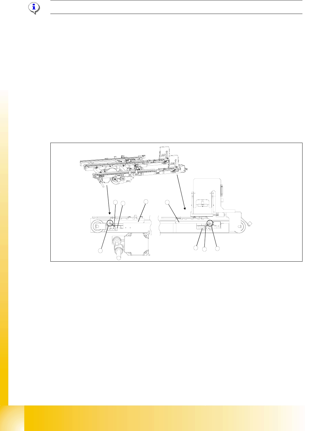
Fig. 11.3 - 21 Setting the maximum and minimum positions of the limit switches (shown here for tower 1)
1 Driver at the transfer position
2 Driver at the zero position
3 Limit switch maximum position with contact roller
4 Limit switch minimum position with contact roller
5 Limit switch holder
6 Contact area driver/limit switch at maximum position
7 Contact area driver/limit switch at minimum position
2
1
5
3
5
4
6
7
1 - 59
Student Guide SIPLACE HF/HF3
Edition 09/2005 11 MTC 2
59
11.3.4.3 Light barriers
WARNING
You may only check and calibrate the light barriers of the feed axis with the correct zero positions,
transfer positions and removal positions of the lifting and feed axes.
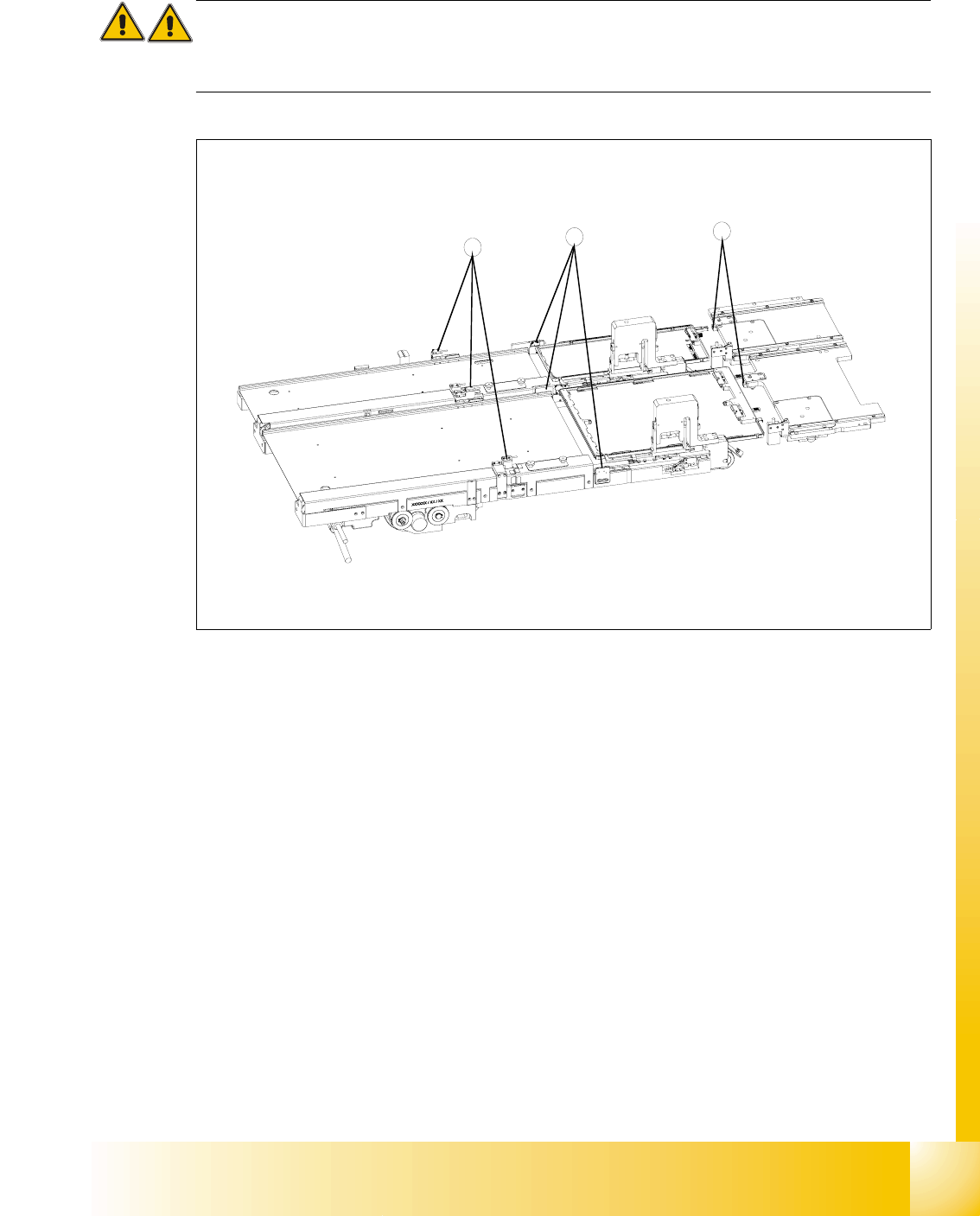
Fig. 11.3 - 22 Light barriers on the feed axes
Key
1 Handle sensor
2 WTC safety query
3 Crash light barriers
Tools and accessories 11
– Adjustment gauge, crash light barriers (03021679-01)
– 1 set of hexagon socket wrenches
Preparatory measures 11
➠ Move the feed axis into the zero position.
3
2
1