SG_FSE_SiplaceHF_HF3_00193901-05_eng.pdf - 第533页
1 - 59 S tudent Guide SIPLACE HF/HF3 Edition 09/2005 1 1 MTC 2 59 1 1.3.4.3 Light barriers WA R N I N G Y ou may only check a nd calibrate the ligh t barriers of th e feed axis with the correct zero positions, transfer p…
1 - 58
Student Guide SIPLACE HF/HF3
11 MTC 2 Edition 09/2005
58
NOTE: Before the limit switches are set, the zero offset and the transfer position must be checked.
➠ Check the zero offset (see section 11.3.2.2).
➠ Check the transfer position (see section 11.3.2.2).
Setting the limit switches 11
➠ Move the feed axis into the transfer position (see section 11.3.2.2).
➠ Set the maximum position of the limit switch above its limit switch holder until there is a
distance of approximately 1 mm between the driver in the transfer position and the contact
roller of the limit switch.
➠ Move the feed axis into the zero position (see section 11.3.2.2).
➠ Set the minimum position of the limit switch above its limit switch holder until there is a distance
of approximately 1 mm between the driver in the zero position and the contact roller of the limit
switch (approximately 10 mm on tower 2).
➠ Check the end positions of the feed axis (see section 11.3.2.2).
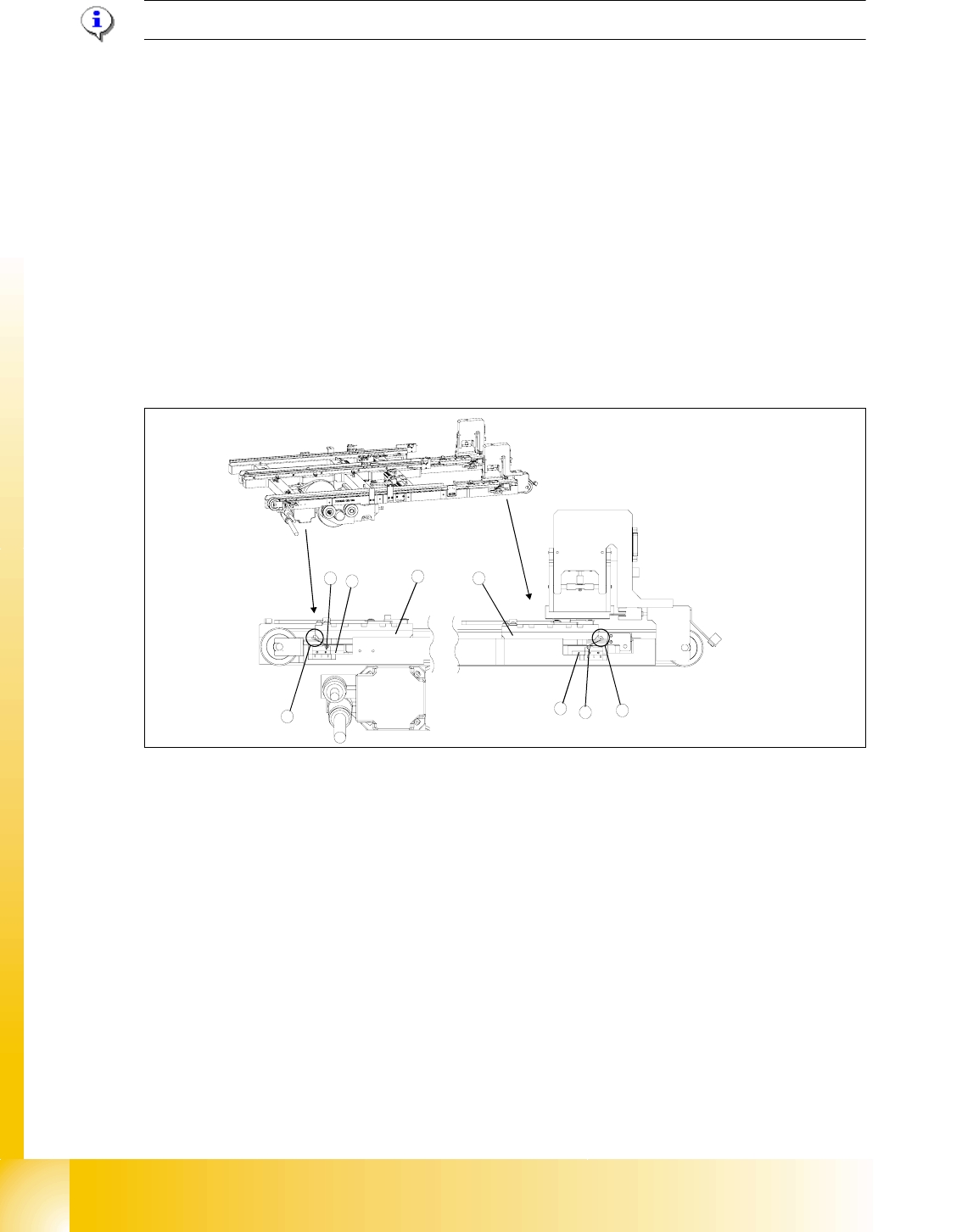
Fig. 11.3 - 21 Setting the maximum and minimum positions of the limit switches (shown here for tower 1)
1 Driver at the transfer position
2 Driver at the zero position
3 Limit switch maximum position with contact roller
4 Limit switch minimum position with contact roller
5 Limit switch holder
6 Contact area driver/limit switch at maximum position
7 Contact area driver/limit switch at minimum position
2
1
5
3
5
4
6
7
1 - 59
Student Guide SIPLACE HF/HF3
Edition 09/2005 11 MTC 2
59
11.3.4.3 Light barriers
WARNING
You may only check and calibrate the light barriers of the feed axis with the correct zero positions,
transfer positions and removal positions of the lifting and feed axes.
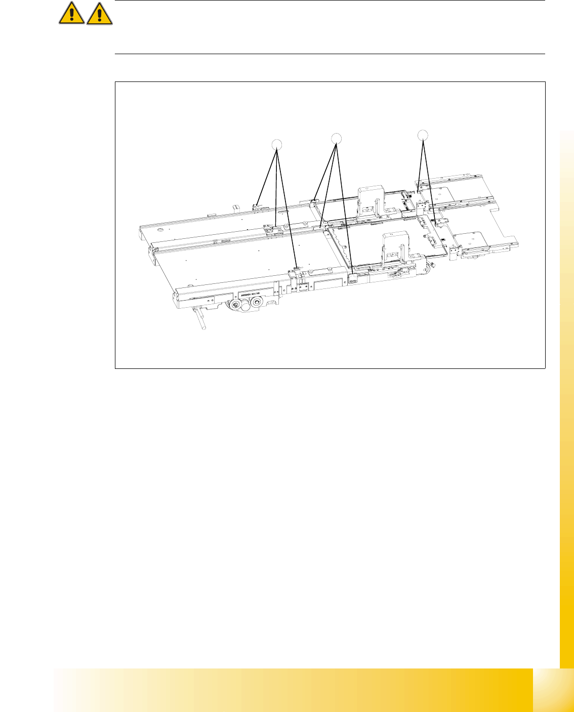
Fig. 11.3 - 22 Light barriers on the feed axes
Key
1 Handle sensor
2 WTC safety query
3 Crash light barriers
Tools and accessories 11
– Adjustment gauge, crash light barriers (03021679-01)
– 1 set of hexagon socket wrenches
Preparatory measures 11
➠ Move the feed axis into the zero position.
3
2
1
1 - 60
Student Guide SIPLACE HF/HF3
11 MTC 2 Edition 09/2005
60
Checking and setting the handle sensors 11
NOTE
The handle sensors each comprise a reflecting light barrier which can detect the handle of the
WTC or the side of the handle of the WTC XL. An LED indicates the switching status of the sensor.
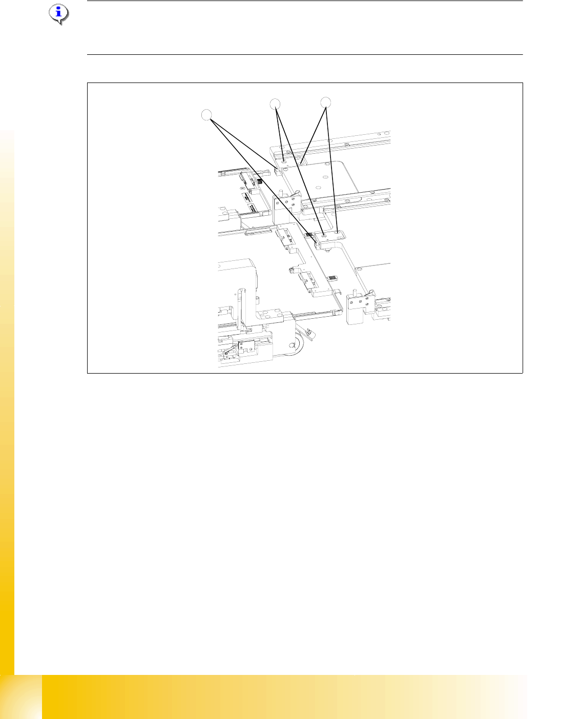
Fig. 11.3 - 23 Checking and setting the handle sensors
Key
1 Reflecting light barriers of the handle sensors
2 Mounting plates with clamping screws
3LEDs
➠ Unscrew the clamping screws of the mounting plate.
➠ Move the mounting plate in the direction of the WTC until the reflecting light barrier responds
(the LED will change its status). Fix the plate in place there.
➠ Ensure that the status of the LED remains the same when you move the locked WTC. If
necessary, move the mounting plate a little further in the direction of the WTC.
➠ Firmly tighten the clamping screws.
3
2
1