SG_FSE_SiplaceHF_HF3_00193901-05_eng.pdf - 第538页
1 - 64 S tudent Guide SIPLACE HF/HF3 1 1 MTC 2 Edition 09/2005 64 1 1.3.4.5 Disengaging mechanism T ools and accessories 11 – 1 set of hexagon socket wrenches Prep aratory measures 11 ➠ Empty the MTC 2 completely (see th…
1 - 63
Student Guide SIPLACE HF/HF3
Edition 09/2005 11 MTC 2
63
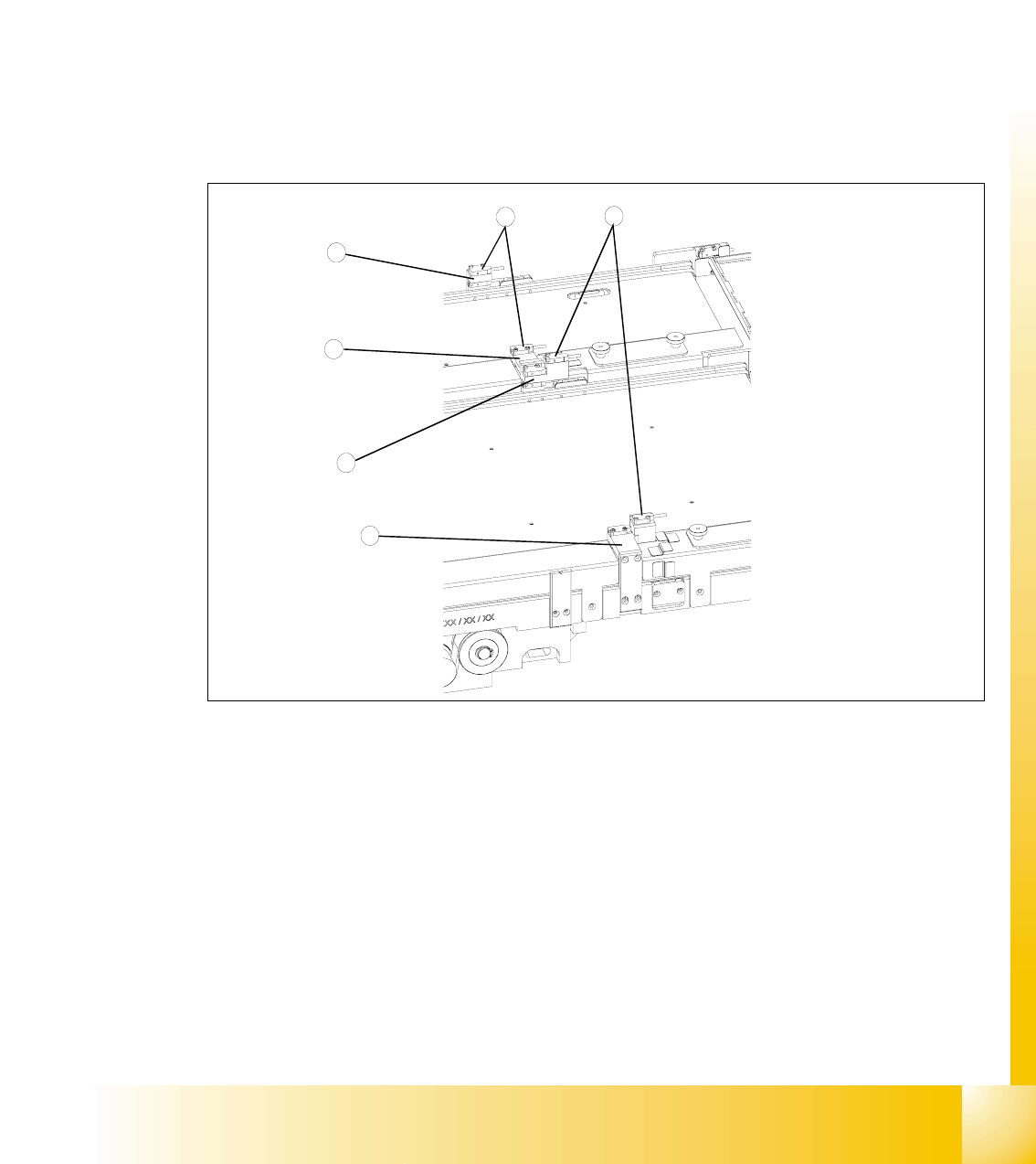
➠ On the adjustment gauge the light barrier should still shine through at a height of 9,75 mm and
at a height of 9,85 mm the light should be interrupted.
➠ Place the adjustment gauge for the crash light barriers along of a empty WPC onto the rail of
the feed axis for tower 2.
➠ Unscrew the clamping screws of the holder for tower 2 and the middle holder (movable section)
and place the bottom light barrier pair onto the middle of the gauge. Ensure that the holders do
not jam in their guide.
➠ Firmly tighten the clamping screws. Ensure that the holders cannot be moved or turned any
more.
➠ At this setting, the bottom light barrier pair should still just shine through at a height of
11.40 mm + 0.05 mm and no longer shine through at a height of 11.50 mm + 0.05 mm.
Fig. 11.3 - 25 Checking and setting the crash light barriers
Key
1 Crash light barriers for tower 1
2 Crash light barriers for tower 2
3 Light barrier holder for tower 1 with clamping screws
4 Middle light barrier holder with clamping screws, base section
5 Middle light barrier holder with clamping screws, movable section
6 Light barrier holder for tower 2 with clamping screws
4
2
1
3
5
6
1 - 64
Student Guide SIPLACE HF/HF3
11 MTC 2 Edition 09/2005
64
11.3.4.5 Disengaging mechanism
Tools and accessories 11
– 1 set of hexagon socket wrenches
Preparatory measures 11
➠ Empty the MTC 2 completely (see the User Manual).
➠ Move the feed axis into the zero position (see section11.3.2.2 ) and engage the driver in the
WTC.
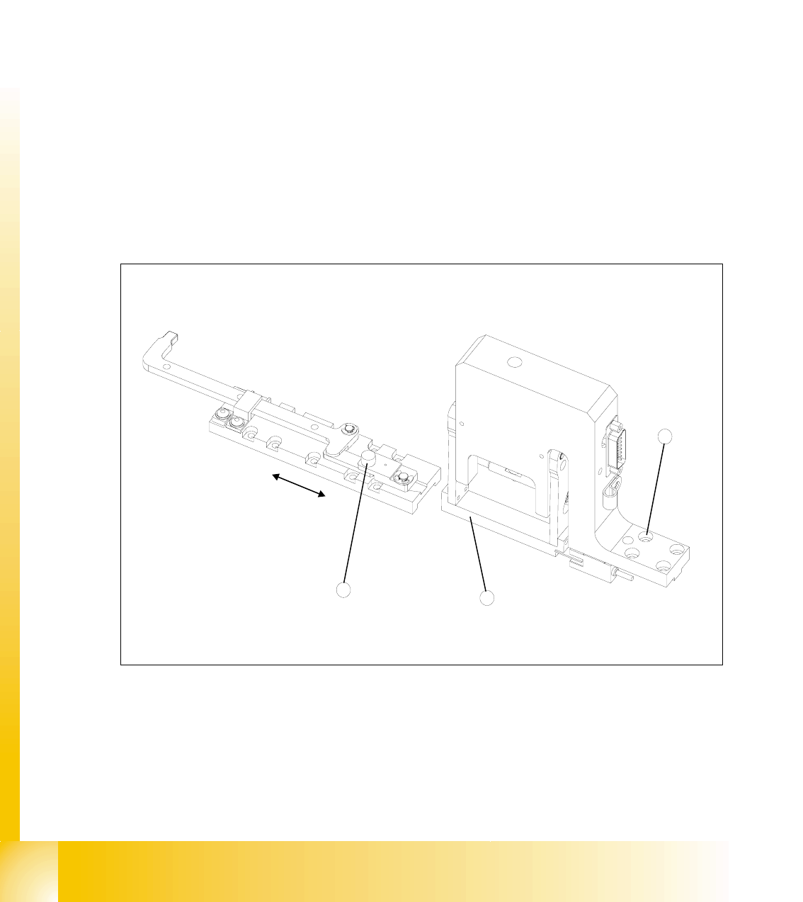
Setting the disengaging mechanism 11
➠ Move the driver over the belt until it lies outside the disengaging mechanism.
➠ Check that the driver in its dead center position engages centrally with the disengaging
aperture when it is moved back.
➠ When the guide roller is pushed through the middle of the aperture, set the position of the
aperture with the 4 securing screws of the disengaging mechanism.
Fig. 11.3 - 26 Setting the disengaging mechanism
Key
1 Driver guide roller in dead center position
2 Disengaging mechanism aperture
3 Disengaging mechanism securing screws
2
3
1
1 - 65
Student Guide SIPLACE HF/HF3
Edition 09/2005 11 MTC 2
65
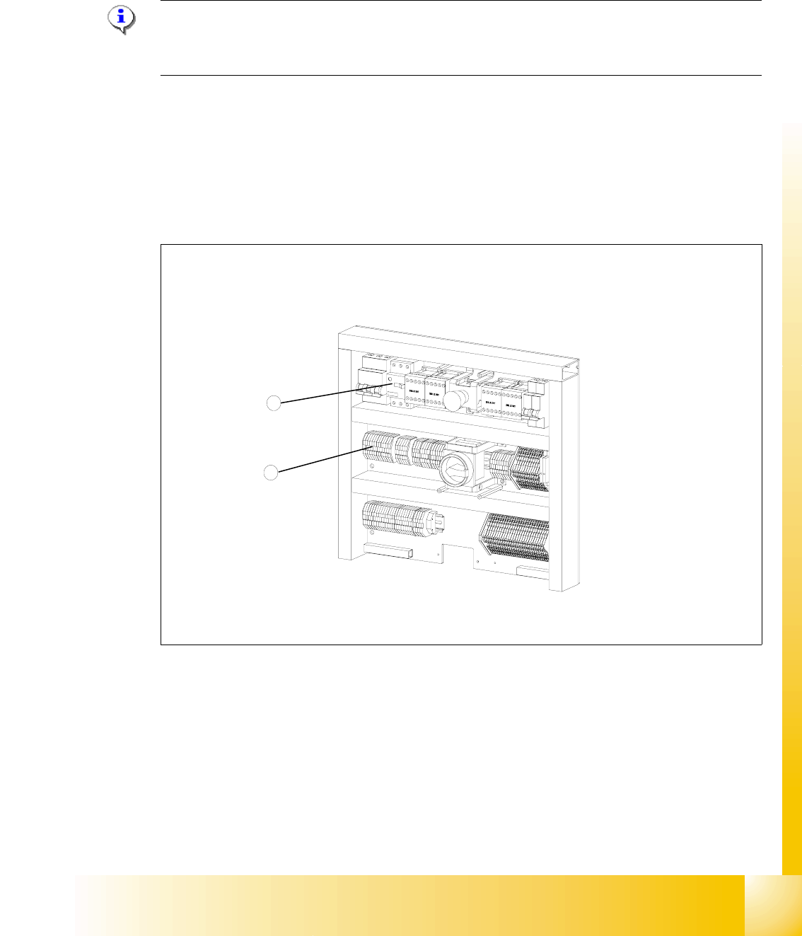
11.3.5 Converting the power supply
To operate the MTC 2 in the USA or in Japan, the power supply needs to be changed from 400
V, 50 Hz to 208/204 V, 50/60 Hz.
NOTE
To convert the power supply from 208/204 V to 400 V, the same procedure must be carried out in
the reverse order.
Tools and accessories 11
– 1 set of screwdrivers
– 3 additional bridges
11.3.5.1 Procedure
Fig. 11.3 - 27 Electronics board
Key
1 Bridges on the voltage distributor terminal X01
2 Motor protection switch
2
1