SG_FSE_SiplaceHF_HF3_00193901-05_eng.pdf - 第540页
1 - 66 S tudent Guide SIPLACE HF/HF3 1 1 MTC 2 Edition 09/2005 66 1 1.3.5.2 V olta ge distributor terminal X01 11 Fig. 1 1.3 - 28 Voltage distributor terminal X01 Key 1 Bridges on the voltag e distributor terminal X01 ➠ …
1 - 65
Student Guide SIPLACE HF/HF3
Edition 09/2005 11 MTC 2
65
11.3.5 Converting the power supply
To operate the MTC 2 in the USA or in Japan, the power supply needs to be changed from 400
V, 50 Hz to 208/204 V, 50/60 Hz.
NOTE
To convert the power supply from 208/204 V to 400 V, the same procedure must be carried out in
the reverse order.
Tools and accessories 11
– 1 set of screwdrivers
– 3 additional bridges
11.3.5.1 Procedure
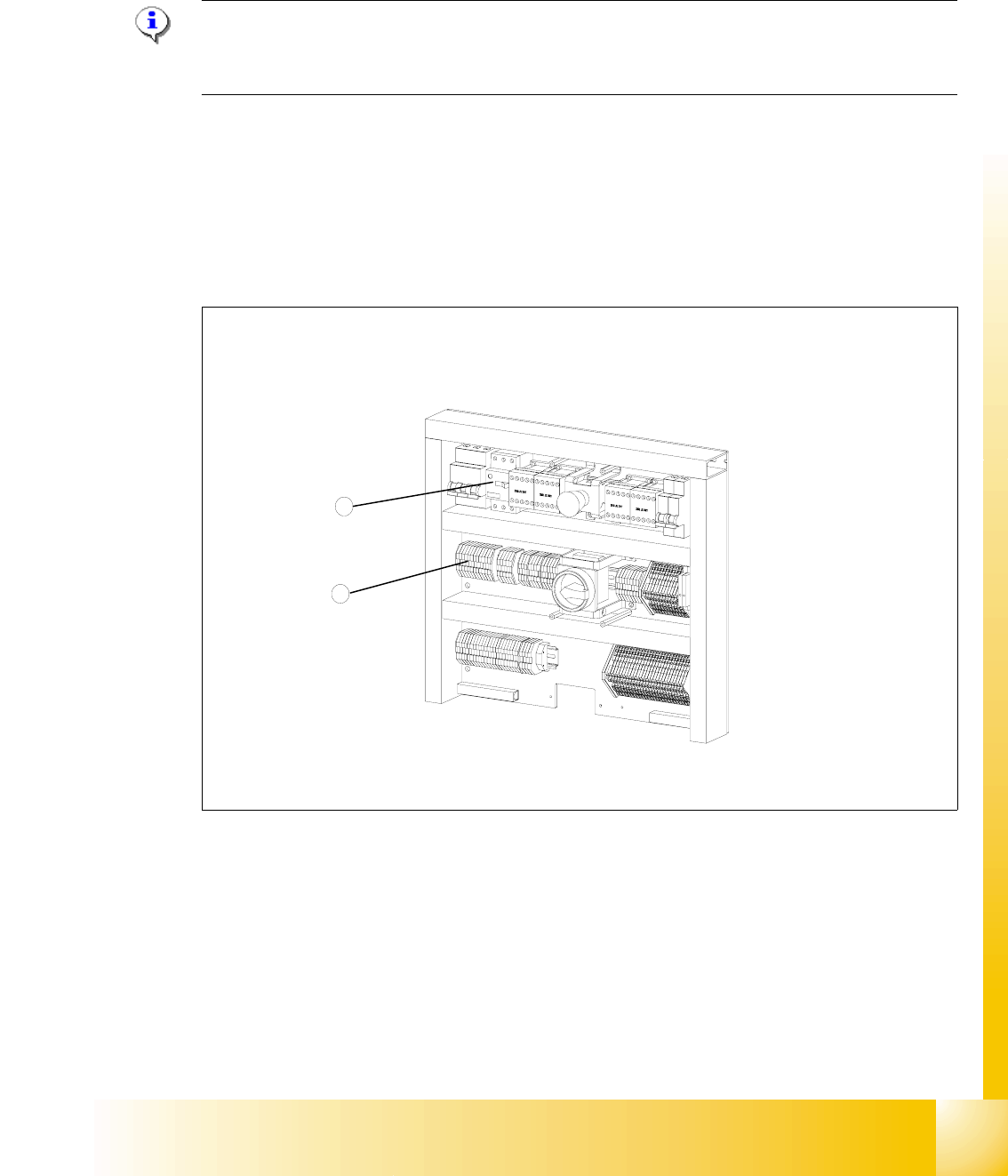
Fig. 11.3 - 27 Electronics board
Key
1 Bridges on the voltage distributor terminal X01
2 Motor protection switch
2
1
1 - 66
Student Guide SIPLACE HF/HF3
11 MTC 2 Edition 09/2005
66
11.3.5.2 Voltage distributor terminal X01
11
Fig. 11.3 - 28 Voltage distributor terminal X01
Key
1 Bridges on the voltage distributor terminal X01
➠ Removing the three bridges between 2-3, 6-7 and 10-11.
➠ Connect the six bridges between 1-2, 3-4, 5-6, 7-8, 9-10 and 11-12.
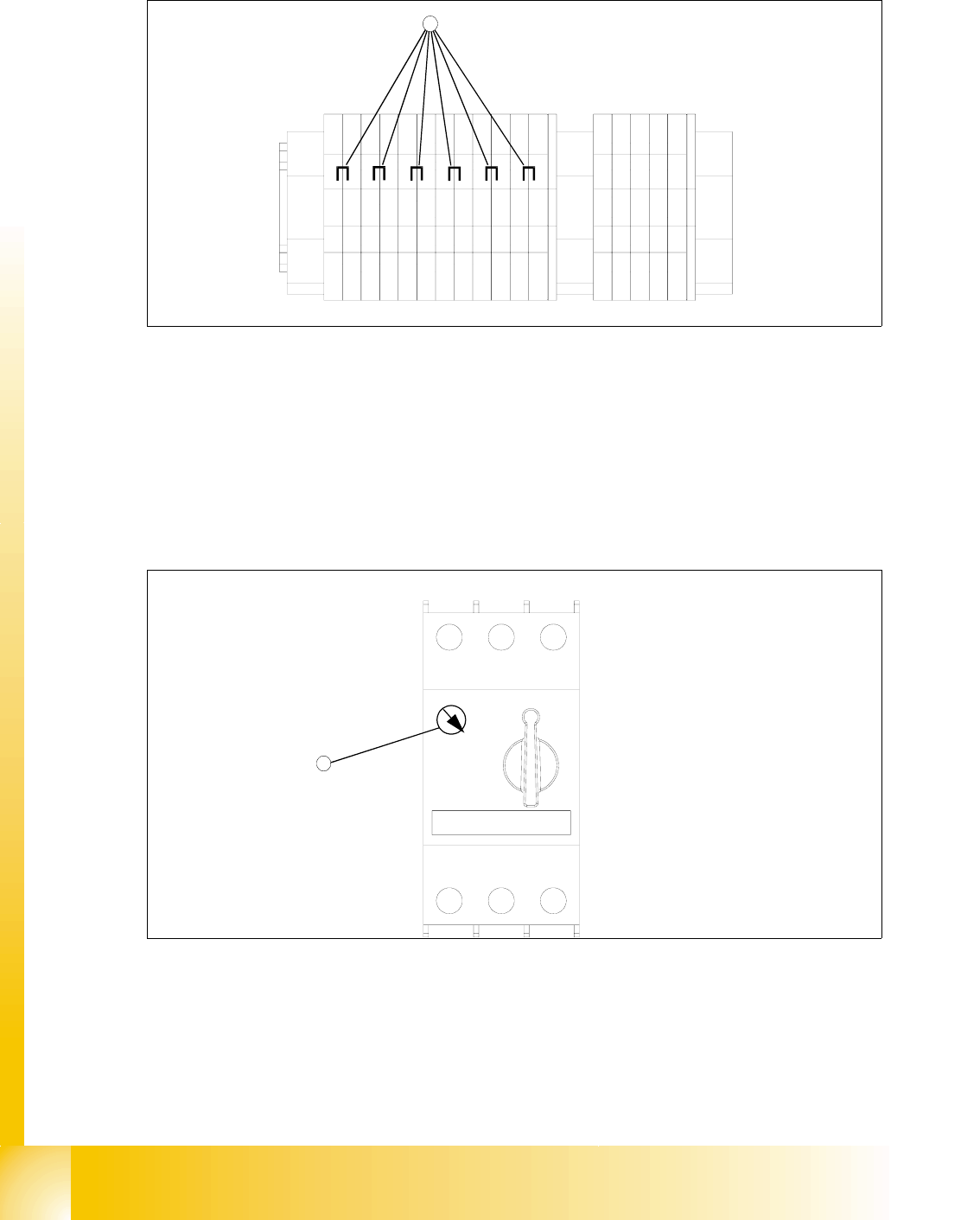
11.3.5.3 Motor protection switch
11
Fig. 11.3 - 29 Motor protection switch
Key
1 Rotary regulator of the motor protection switch
➠ Do not switch the rotary regulator of the motor protection switch, if you converting the power
supply. It is always 3.5 A.
-X01
1
2
3
45
6789
10
11
12
11
11
3,5A
5,0A

1 - 67
Student Guide SIPLACE HF/HF3
Edition 09/2005 11 MTC 2
67
11.3.6 Machine Data
NOTE: The machine parameters listed are only an example of a data record. The individual
values can be different for every MTC 2.
WARNING
Incorrectly set machine data can result in a crash between the lifting and feed axes or at the limit
positions of these axes.
11.3.6.1 General machine parameters
Software version: Date 11.2004
Serial number, MTC 2: 214
Delta fiducial transfer position: 10000
11.3.6.2 Machine parameters for tower 1
Machine parameters for the lifting axis on tower 1 11
Offset, zero position: -560.300 mm
Position of operator removal position, cassette 1: 0 mm
Position of operator removal position, cassette 2: 103.150 mm
Position of operator removal position, cassette 3: 206.250 mm
Position of operator removal position, cassette 4: 309.450 mm
Position of operator removal position, cassette 5: 412.600 mm
Position of WTC removal position, cassette 1: 28.300 mm
Position of WTC removal position, cassette 2: 131.500 mm
Position of WTC removal position, cassette 3: 234.500 mm
Position of WTC removal position, cassette 4: 337.800 mm
Position of WTC removal position, cassette 5: 440.950 mm
Minimum position: -3.233 mm
Maximum position: 573.472 mm
Service position: 165.000 mm