SG_FSE_SiplaceHF_HF3_00193901-05_eng.pdf - 第552页
1 - 78 S tudent Guide SIPLACE HF/HF3 1 1 MTC 2 Edition 09/2005 78 1 1.4.4 Setting the CAN bu s addr ess at the master drive PMU It is necessary to enter the addresses of the feed and lif ting axes on the PMU’s (Parameter…

1 - 77
Student Guide SIPLACE HF/HF3
Edition 09/2005 11 MTC 2
77
11.4.3 Factory settings
Reset the Master drives to the define defaults
NOTE
When setting factory defaults, the axis concerned must not be subject to position control.
You must change 3 Parameters to define the defaults after this you can download the parameter
set for the axis.
1. Change Parameter P053 from 7 to 6 (This value is a Binary code 0111
→ 0110).
2. Set Parameter P060 from 7 to 2.
3. Change Parameter P970 from 1 to 0. Parameter-Reset is started.
Check the serial interface and CAN Bus address after RESET: 11
1. Adjust the V24 (RS232) Interface.
Parameter P700 = 0
Parameter P701
→ Index 1= 8 (8 = Baud rate 38400).
2. Check the address for Can -Bus Parameter P918.
3. Download the Parameter set for the Axis with the Laptop.
1 - 78
Student Guide SIPLACE HF/HF3
11 MTC 2 Edition 09/2005
78
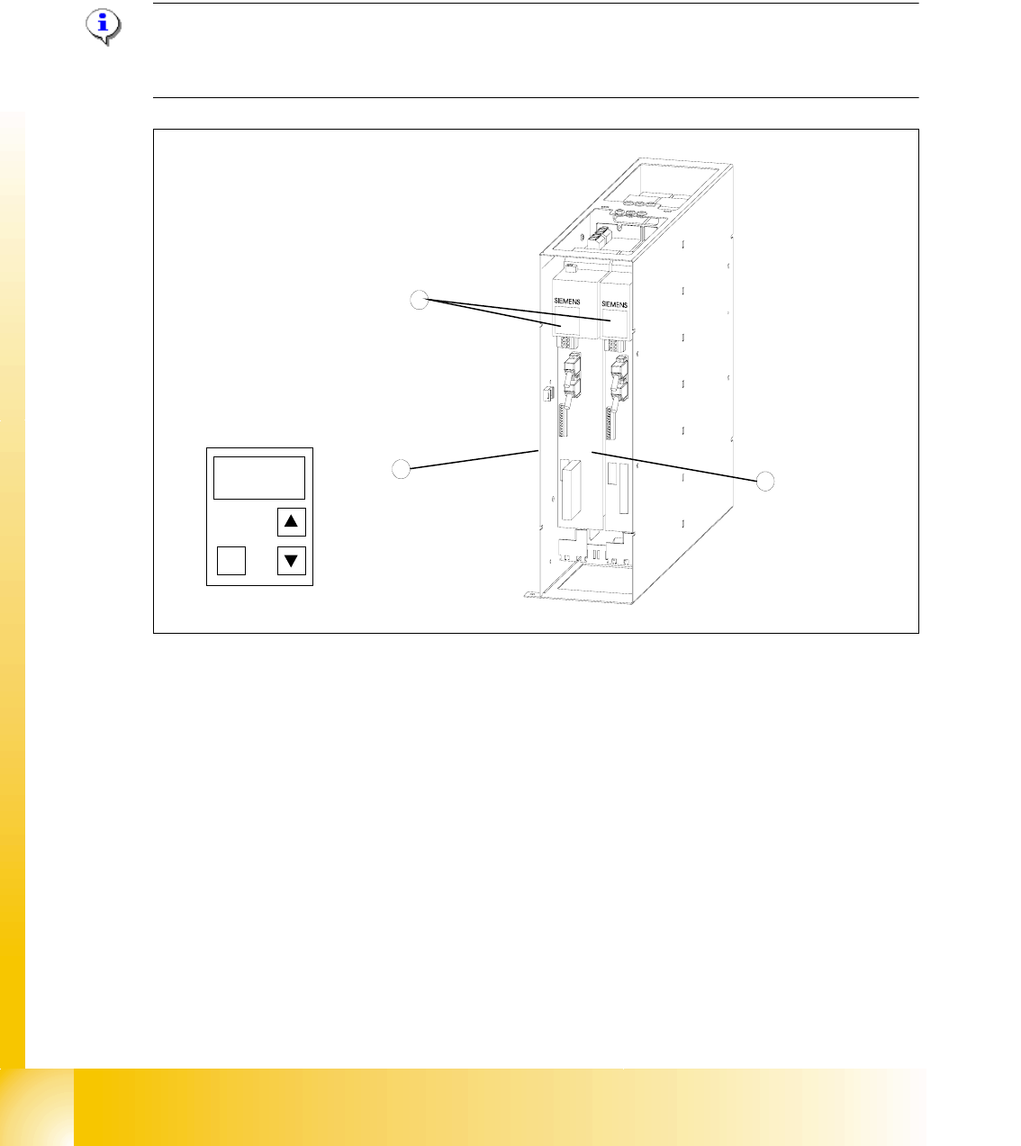
11.4.4 Setting the CAN bus address at the master drive PMU
It is necessary to enter the addresses of the feed and lifting axes on the PMU’s (Parameterization
Units) for the Master drives on initial commissioning of the MTC and after the replacement of the
Master drives. This can be performed external to the MTC. The Master drives must be supplied
with 24 V DC. The control for the related axis must be shut down.
Note:
For setting the CAN Bus address you could use the software "Drive Monitor". When you adjust
the CAN Bus address manually please use the instruction in chapter 13.3.
Fig. 11.4 - 3 Masterdrives of the lifting and feed axes (shown here for tower 1)
Key
1 Masterdrive of the lifting axis for tower 1
2 Masterdrive of the feed axis for tower 1
3 Control panels
These brief instructions show how to enter the address for the Masterdrive of the lifting axis for
tower 1. The procedure is similar for the other axes (but with different addresses). For more
detailed information, see the chapter "Parameterization" in the user manual for "SIMOVERT
MASTERDRIVES".
1
2
3
P
1 - 79
Student Guide SIPLACE HF/HF3
Edition 09/2005 11 MTC 2
79
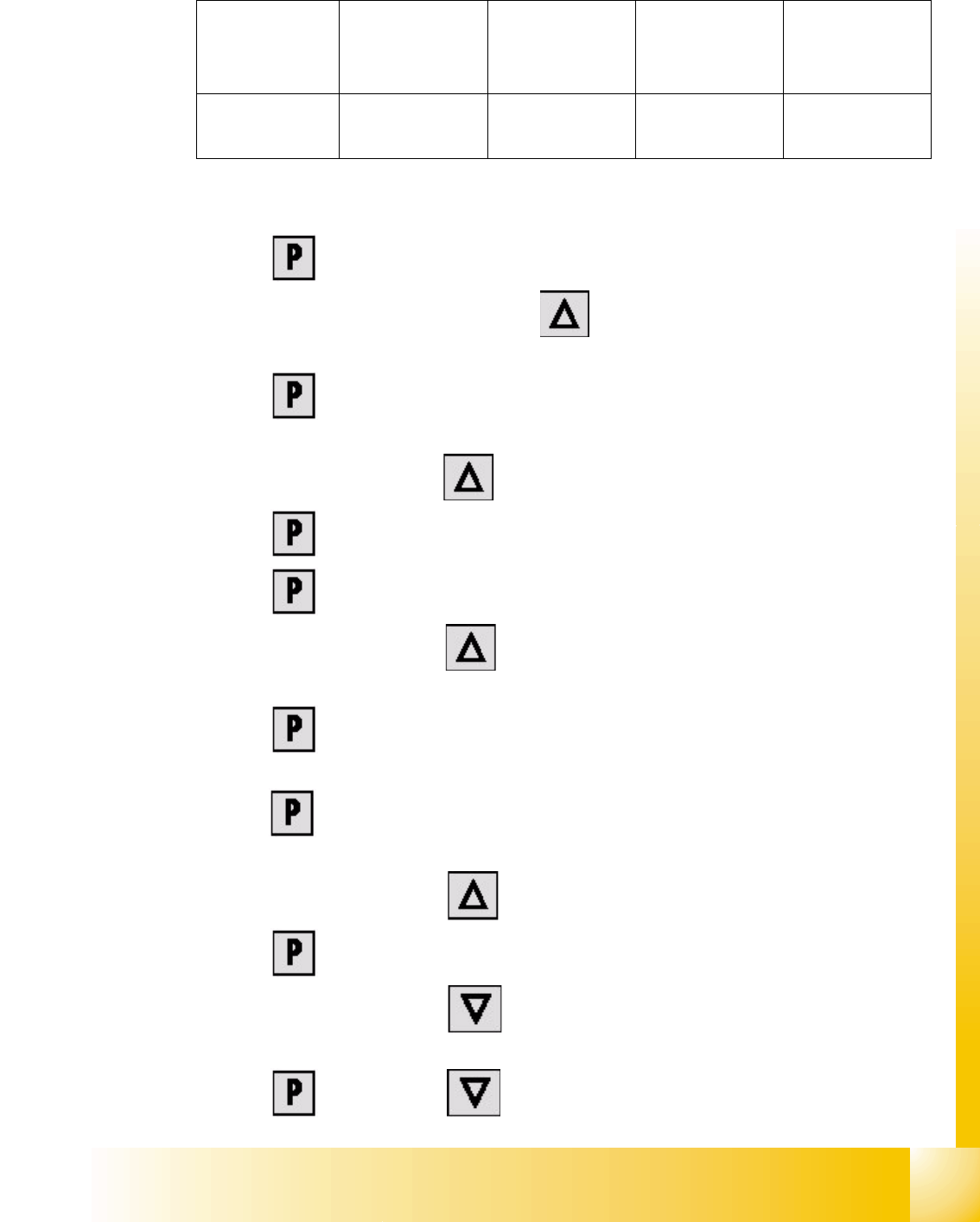
The following addresses are provided for the lifting and feed axes:
Table 11.4 - 1 Addresses of the Masterdrives
1 Press , to go to the parameter numbers.
2 Step through the parameter numbers with , until "
P060" appears on the seven segment
display. This is the menu selection.
3 Press . A number appears on the display. This is the "Parameter menu" menu
command.
4 Step through the options with , until "
4" is displayed. ("4" means "Module configuration").
5Press . "
004" is displayed. This is the status indicator for "Module configuration".
6 Press to go to the parameter numbers. "
P060" is displayed.
7 Step through the options with until "
P918" appears on the seven segment display. This
is the parameter number for the bus address.
8 Press to go to the parameter index. "
001" indicates that this is Index 1 (an index is
always indicated by a small line).
9 Press to go to the parameter value. "
1" is displayed. This is the address of the lifting axis
for tower 1.
10 Set the relevant address with (see
Table 11.4 - 1).
11 Press to return to the parameter numbers. "
P918" is displayed again.
12 Step through the options with until "
P060" appears. Now you are back in the menu
selection.
13 Press and set "
1" with . This returns you to the menu command "Parameter
Lifting axis
Tower 1
Feed axis
Tower 1
Lifting axis
Tower 2
Feed axis
Tower 2
Address
1234