SG_FSE_SiplaceHF_HF3_00193901-05_eng.pdf - 第554页
1 - 80 S tudent Guide SIPLACE HF/HF3 1 1 MTC 2 Edition 09/2005 80 menu". 14 Press . " 009 " is displayed. 15 Press . " P60 " is displayed. 16 Set " r000 " with . 17 Press . The initial …
1 - 79
Student Guide SIPLACE HF/HF3
Edition 09/2005 11 MTC 2
79
The following addresses are provided for the lifting and feed axes:
Table 11.4 - 1 Addresses of the Masterdrives
1 Press , to go to the parameter numbers.
2 Step through the parameter numbers with , until "
P060" appears on the seven segment
display. This is the menu selection.
3 Press . A number appears on the display. This is the "Parameter menu" menu
command.
4 Step through the options with , until "
4" is displayed. ("4" means "Module configuration").
5Press . "
004" is displayed. This is the status indicator for "Module configuration".
6 Press to go to the parameter numbers. "
P060" is displayed.
7 Step through the options with until "
P918" appears on the seven segment display. This
is the parameter number for the bus address.
8 Press to go to the parameter index. "
001" indicates that this is Index 1 (an index is
always indicated by a small line).
9 Press to go to the parameter value. "
1" is displayed. This is the address of the lifting axis
for tower 1.
10 Set the relevant address with (see
Table 11.4 - 1).
11 Press to return to the parameter numbers. "
P918" is displayed again.
12 Step through the options with until "
P060" appears. Now you are back in the menu
selection.
13 Press and set "
1" with . This returns you to the menu command "Parameter
Lifting axis
Tower 1
Feed axis
Tower 1
Lifting axis
Tower 2
Feed axis
Tower 2
Address
1234

1 - 81
Student Guide SIPLACE HF/HF3
Edition 09/2005 11 MTC 2
81
11.4.5 Downloading parameter sets
Requirements: 11
– CD ROM Drive Monitor
– Cables for laptop and master drives (03021720-01)
– Parameter set for lifting axis Tower 1 and Tower 2
– Parameter set for feed axis Tower 1 and Tower 2
– Simovert Masterdrive for the Lifting axis (00354979-01)
– Simovert Masterdrive for the Feed axis (00354980-01)
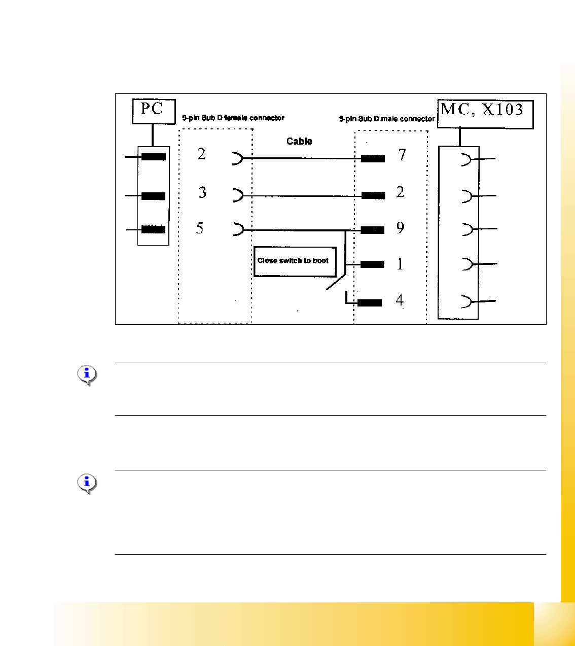
Fig. 11.4 - 4 Cable configuration for the connection between the laptop and the master drive
NOTE
Please don‘t forget the jumper between pin 9 and 1. The switch is not necessary for downloading
the parameter sets.
Installation Drive Monitor 11
Note:
You could use the software "Drive Monitor" for the MTC 1 too. The softwareversion on the MTC 1
is 1.5.
Installation can only be carried out with administrator rights.
Prior to installation, it may be necessary to create a directory with the name "Parameter sets".