SG_FSE_SiplaceHF_HF3_00193901-05_eng.pdf - 第69页
1 - 43 S tudent Guide SIPLACE HF/HF3 Edition 09/2005 2 Overview 43 2.2.17.2 Construction single conveyor The single conveyor co nsist oft the in put convey or , two placements areas, in termediate conveyo r and output co…

1 - 42
Student Guide SIPLACE HF/HF3
2 Overview Edition 09/2005
42
Control the PCB inside the conveyors 2
The PCB will be checked with light barriers (transmitter module and a receiving module). The light
barriers are positioned above the transportbelts and they point past the transportbelt.The light bar-
riers stopps the PCB in the input conveyor, intermediate conveyor and output conveyor.
With the signal from the light barrier the brake application of the DC motor is starting, only in the
placement area. The PCB move in a unchangable time period (100ms) with their reduced speed
to the stopper position(Laser) that control via software. Indepent of heavy and light PCB board we
start the brake application to the right time so that we move always approx. 100ms to the stopper.
PCB Stopper 2
The PCB in the placement area will be stop with a laser light barrier. The laser light barrier looks
at the front edge of the PCB and stop them. In this case we do not have a shock against the stop-
per.
The position accuracy of the PCB is +/-0,5mm.
– Mechanical stopper for long boards up to 610mm is an option
Lifting table 2
In each placement area we have one or two independent working lifting tables (dual/single con-
veyor). The lifting table drive is working indirectly via pneumatic cylinder controlled of a 5/3 way
valve. Different thickness of PCB is automatically compensate. The guide for the lifting table plate
in the vertical direction (up/down) is defined at four point. The lifting distance is determined via a
incremental system.
The upper position will be controlled over the measurement system with a incremental encoder
and via the current of the transport motor.
The lower position will be checked with the measurement system and a BERO on the pneumatic
cylinder.
Additional we check the time which we need in both directions.
The clearance under the PCB is 40mm.
You can not use the old 74 mm high PCB supports on the HF machines.
The dual conveyor can be used as an single conveyor when you move the conveyor rails of track
2 to the limits (depend on the Softwareversion 505).
1 - 43
Student Guide SIPLACE HF/HF3
Edition 09/2005 2 Overview
43
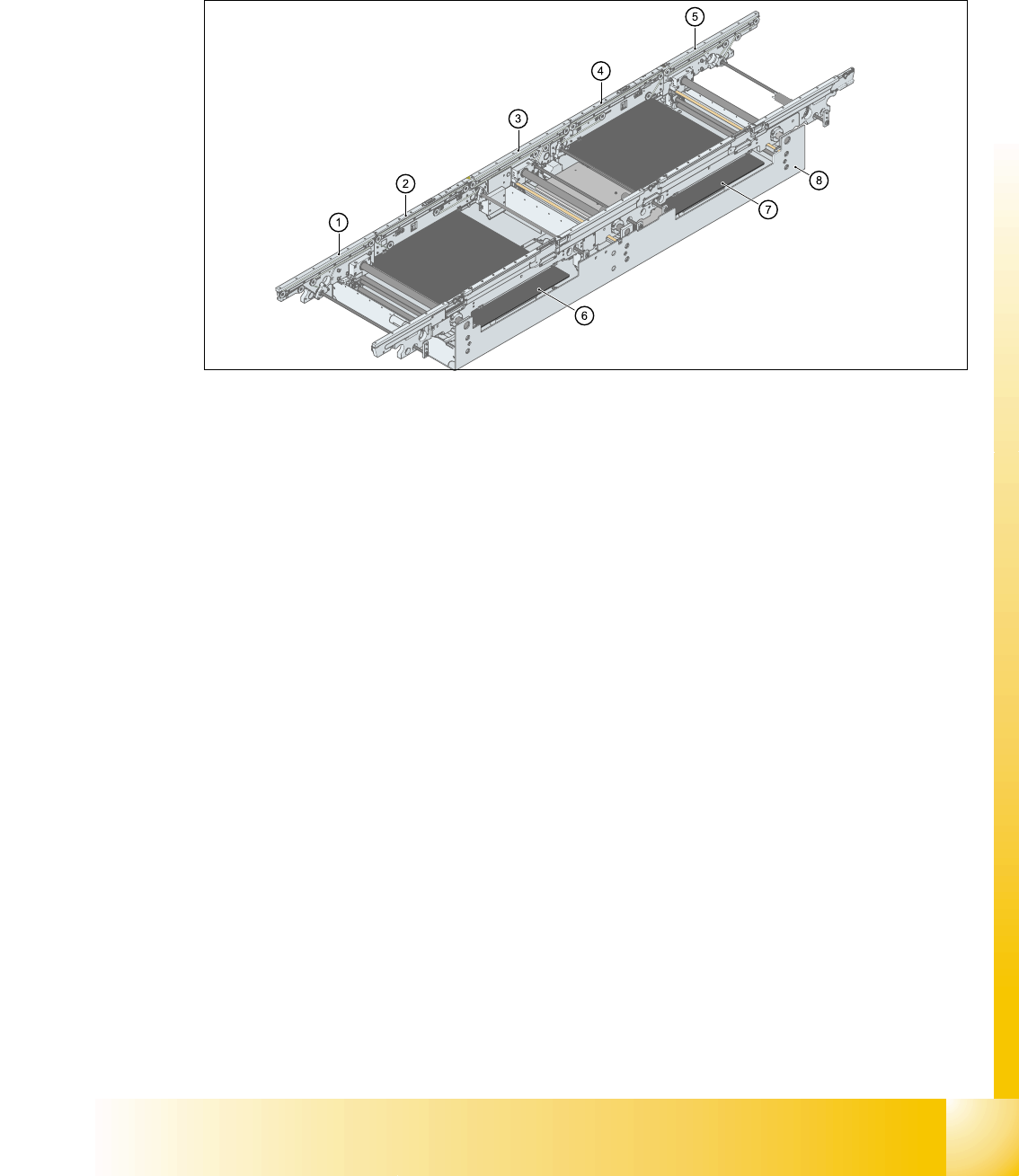
2.2.17.2 Construction single conveyor
The single conveyor consist oft the input conveyor, two placements areas, intermediate conveyor
and output conveyor. Every conveyor had an automatic width adjustment and a lifting table for
clamping the PCB..
2
Fig. 2.2 - 30 Construction PCB conveyor
1. Input conveyor
2. Conveyor at placement area 1
3. Intermediate conveyor
4. Conveyor at placement area 2
5. Output conveyor
6. Lifting table 1
7. Lifting table 2
8. mounting frame transport
1 - 44
Student Guide SIPLACE HF/HF3
2 Overview Edition 09/2005
44
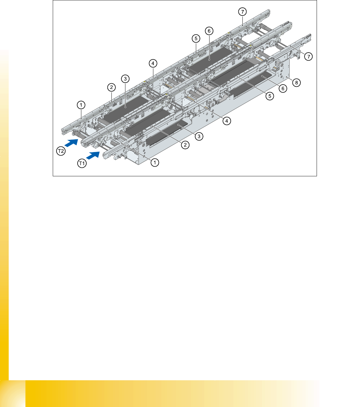
2.2.17.3 Construction dual conveyor
Dual conveyor has two transportation tracks (1 and 2). At the standard conveyor, the fixed con-
veyorside from every transportation track is on the right side. The fixed conveyor side on the left
side is available.
2
Fig. 2.2 - 31 Construction dual conveyor
1. Input conveyor
2. Conveyor at placement area 1
3. Lifting table PA 1
4. Intermediate conveyor
5. Conveyor at placement area 2
6. Lifting table PA 2
7. Output conveyor
8. mounting frame of transport