SG_FSE_SiplaceHF_HF3_00193901-05_eng.pdf - 第78页
1 - 8 S tudent Guide SIPLACE HF/HF3 3 Communication and Control Edition 09/2005 8 3.2.3 Machine Controller Communication For the calculatio n of the ’ pick up coordinates’ the MC add the pick up correction value s (forme…
1 - 7
Student Guide SIPLACE HF/HF3
Edition 09/2005 3 Communication and Control
7
Compiling the placement position (X/Y coordinates and angle) 3
following values are taken in account for calculating the theoretical placement position:
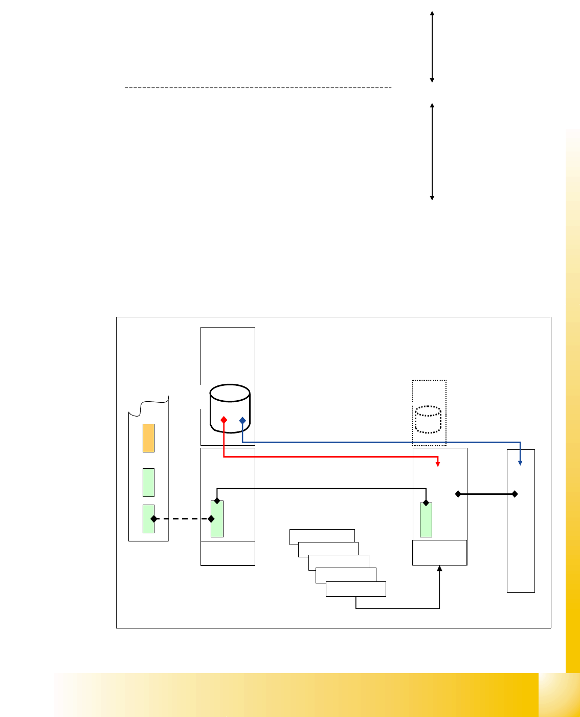
3.2.2 Communication on HF placement machine
The placement data files, stored at the hard drive, are compiled at the station computer. This com-
piling add the calibrated values, taken during calibration in Sitest, to the pick up and placement
data.
Fig. 3.2 - 3 communicaton on HF
Compile run
SIPLACE Pro
Compile run
station computer
• PCB angle in conveyor (how is the PCB in the transport,
0,90,180,270 degree?).
• PCB zero point offset
• placement position on PCB
• fixed PCB corner
• offset PCB - component camera
• segment offset 1
• segment offset 2
• mapping values
• fine calibration values
Axis controller
Axis controller
Axis controller
Axis controller
Machine
Controller
Station
Computer
Compiled
data LC
aktuell.nu
aktuell.rs
XXX_12.gf
XXX_5.mk
...
Compile
run SC
MVS
340
Axis controller
HS3L
CAN BUS 1Mbit/s
1 - 8
Student Guide SIPLACE HF/HF3
3 Communication and Control Edition 09/2005
8
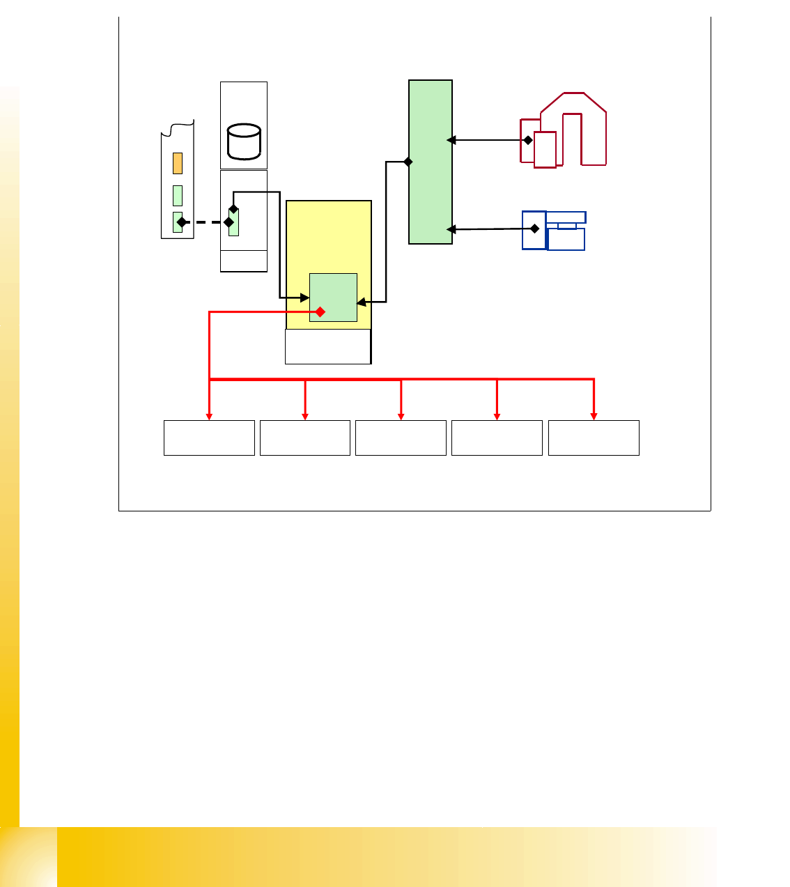
3.2.3 Machine Controller Communication
For the calculation of the ’pick up coordinates’ the MC add the pick up correction values (former
pick up offsets) to the pick up coordinates.
For the calculation of the
’placement coordinates’ the MC add the PCB position correction values
and the component correction values (from camera evaluation) to the placement coordinates.
Fig. 3.2 - 4 communication with MC
X-Axis
controller
SC
MVS
340
Machine
Controller
Y-Axis
controller
Star-Axis
controller
Z-Axis
controller
DP-Axis
controller
Placement
data at MC
+
target position for
pick-up / placement to axis
controller from MC
1 - 9
Student Guide SIPLACE HF/HF3
Edition 09/2005 3 Communication and Control
9
3.3 CAN Bus
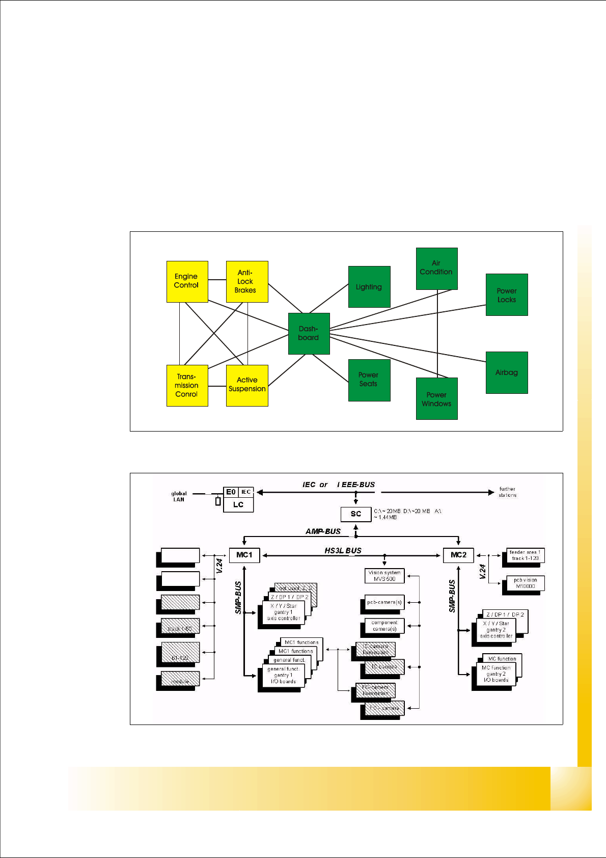
3.3.1 History of CAN
The development of CAN began when more and more electronic devices were implemented into
modern motor vehicles. Examples of such devices include engine management systems, active
suspension, ABS, gear control, lighting control, air conditioning, airbags and central locking. All
this means more safety and more comfort for the driver and of course a reduction of fuel consump-
tion and exhaust emissions.
Fig. 3.3 - 1 communication via cable connection
Fig. 3.3 - 2 communication e.g. on Siplace S15 machine