SG_FSE_SiplaceHF_HF3_00193901-05_eng.pdf - 第83页
1 - 13 S tudent Guide SIPLACE HF/HF3 Edition 09/2005 3 Communication and Control 13 3.3.2.3 CSMA: Collusion Detectection When the bus is free any unit may st art to transm it a message. The u nit with the message of th e…
1 - 12
Student Guide SIPLACE HF/HF3
3 Communication and Control Edition 09/2005
12
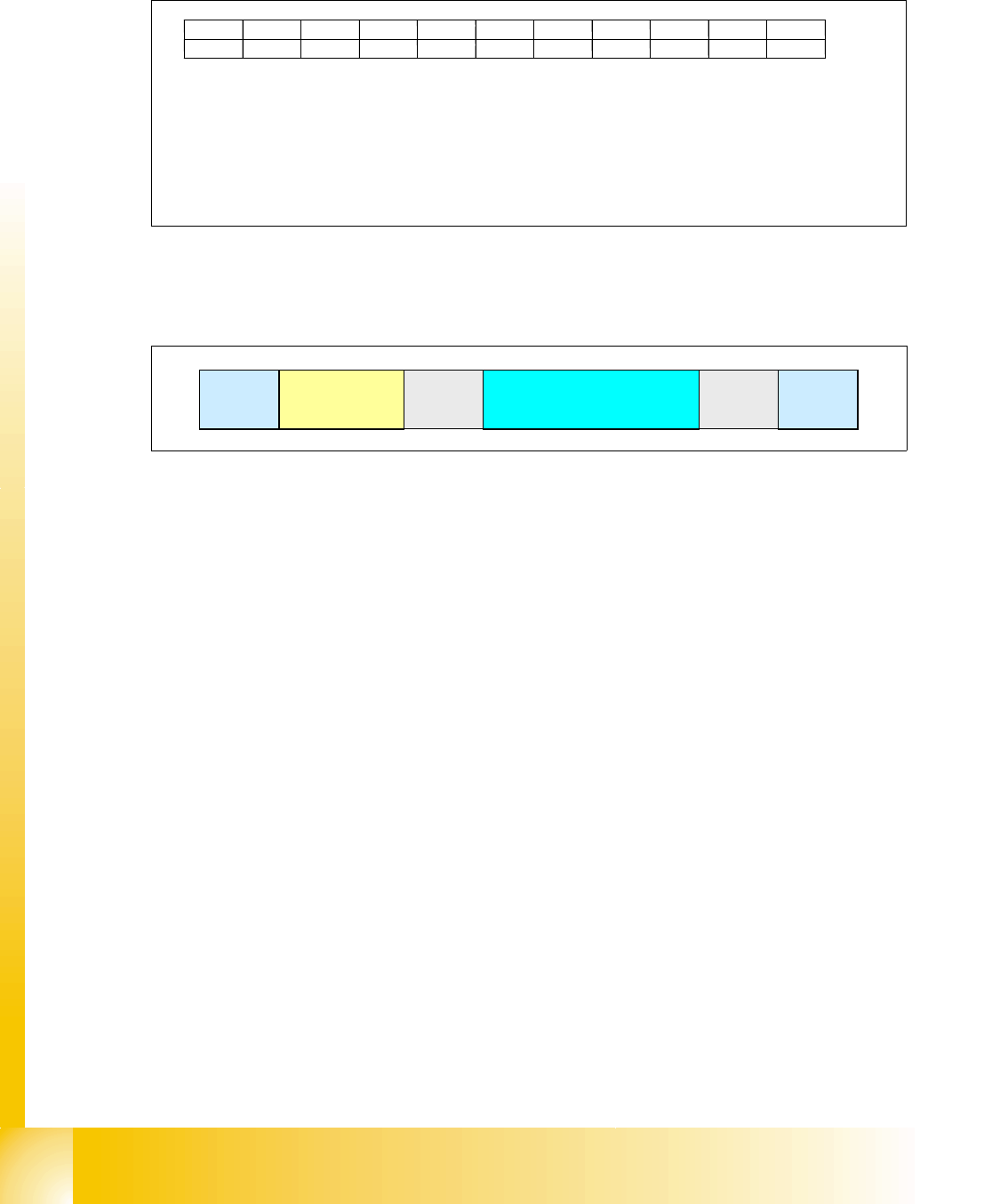
3.3.2.1 11 Bit Identifier
The CAN bus system is using the 11 Bit identifier for addressing the different CAN objects
Fig. 3.3 - 6 11 bit identifier
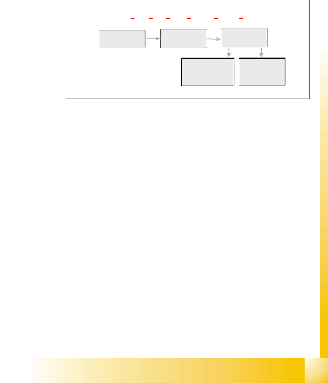
3.3.2.2 CAN Bus protocol
Fig. 3.3 - 7 CAN-bus protocol
Start: 3
– determines the telegram start. After this bit is set, no other user of the CAN bus is able to
send. Even 2 or more user set this bit at the same time, the arbitration decides the highest
priority. The address with the highest priority is allowed to send the telegram.
Address: Identifier field (11 bit identifier) 3
– the value of this number is also the prority for the bus access.
Control information:
3
– contains reserved bits and 4 bit DLC: Data Length Code.
Data field:
3
– contains the user information from 0 byte to maximun 8 byte. The transfer of a byte begins
with the most significant bit (the bit with the highest value).
CRC sequence and CRC delimiter = CRC filed (cyclic redundancy check): 3
– each message is combined with a CRC word. Therefore it recognizes messages which are
at least not in an origin state while disturbances.
End:
3
– the end of the length recognition is 7 bit.
Bit 10 Bit 9 Bit 8 Bit 7 Bit 6 Bit 5 Bit 4 Bit 3 Bit Bit 1 Bit 0
KKCCCCPPTTT
node type (K) CAN object (C) gantry number (P) telegram type (T)
depends on 00: section 1 000 command
node type 01: section 2 001 message
10: section 3
11: section 4
00: heads
01: axis
10: co table
11: reserved
start
address
(11 bit identifier)
control
information.
data (0-8 bytes user information) CRC
end
1 - 13
Student Guide SIPLACE HF/HF3
Edition 09/2005 3 Communication and Control
13
3.3.2.3 CSMA: Collusion Detectection
When the bus is free any unit may start to transmit a message. The unit with the message of the
highest priority is at first.
h
Fig. 3.3 - 8 CSMA: collusion detection
3.3.2.4 CAN Bus Arbitration
In CAN networks, there is no addressing of subscribers or stations in the conventional sense, but
instead, prioritized messages are transmitted. A transmitter sends a message to all CAN nodes
(broadcasting). Each node decide on the basis of the identifier received whether it should process
the message or not. The identifier determines the priority that the message enjoys in competition
for bus access. The relatively simplicity of the CAN chips interlaces make applications program-
ming relatively simply.
Whenever the bus is free, any unit may start to transmit a message. If 2 or more units start trans-
mitting messages at the same time, the bus access conflict is resolved by bitwise arbitration using
IDENTIFIER.
The mechanism of arbitration guarantees that neither information nor time is lost. A DATA FRAME
prevails over the REMOTE FRAME. During arbitration every transmitter compares the level of the
bit transmitted with the level that is monitored on the bus. If these levels are equal the unit may
continue to send. When a recessive level is sent and a dominant level is monitored, the unit has
lost arbitration and must withdraw without sending one more bit.
Multi master:
When the bus is free any unit may start to transmit a message. The unit with the message of the
highest priority is transmitted at first.
bus access
low waiting time
for high prioritized
telegrams
CSMA / CD: Carrier Sense Multiple Access by Collusion Detection
in case of collusion,
the members with
the lower priority
start again later
Carrier Sense
Multiple Access
(CSMA)
ollision
C
Detection
(CD)
1 - 14
Student Guide SIPLACE HF/HF3
3 Communication and Control Edition 09/2005
14
Arbitration: state of matter diagram 3
Fig. 3.3 - 9 flow chart bus arbitration
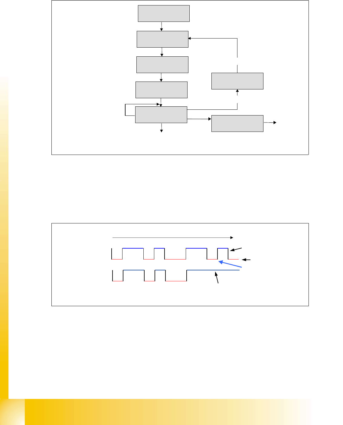
There are two bus states, called ’dominant’ and ’recessive’. The bus logic uses a ’Wired-AND’
mechanism, that is,
’dominant bits’ (equivalent to the logic level ’zero’) overwrite the ’recessive
bits’
(equivalent to the logic level ’one’).
Example: Arbitration with bit by bit detection of 2 member.
3
Fig. 3.3 - 10 CAN- bus arbitration with 2 member
waiting if bus is free
bit SoF
bus in receiving state
1st bit of arbitration
transmitted
compare transmitted bit
level with bus level
bus in error state
arbitration lost?
recessive bit on dominant bus state
all arbitration bits are transmitted,
send control field and data field
next bits
START: Any member
will send a message
11 10 9 8 7 6 5 4 3 2 1 0
recessive (logical high)
dominant (logical low)
member 1 wins arbitration here
member 2 looses arbitration here
and switch in receiving state
identifier member 1 1
Bit
identifier member 2 2