SG_FSE_SiplaceHF_HF3_00193901-05_eng.pdf - 第93页
1 - 23 S tudent Guide SIPLACE HF/HF3 Edition 09/2005 3 Communication and Control 23 3.3.9.1 Connector on I/O module Fig. 3.3 - 20 overview CAN I/O module Legend : (1) DIP Switches X1 CAN interface connector and RS232 ana…
1 - 22
Student Guide SIPLACE HF/HF3
3 Communication and Control Edition 09/2005
22
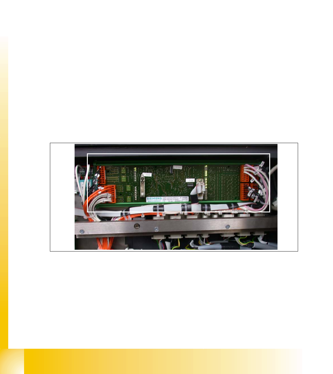
3.3.9 CAN I/O Module (SLIO) HF up to MA.No. xx
Two CAN Bus I/O modules are integrated in the different section of the HF machine. Both modules
are fully identical
Product characteristics:
– micro controller with integrated CAN controller
– data memory
– programm memory (flash)
– CAN interface with 9 pin connector and address alignment
– 16 digital Output 24 V with status LED
– 24 digital Input 24 V with status LED
– download interface
– power supply 5 V and 24 V
8 digital inputs can be logical matched by using an FPGA (free programmable gate array), which
is used for the safety messages input.
Fig. 3.3 - 19 CAN I/O module section 2, main distributor
A extention board for ONE-Wire- Bus is mounted at HF3 machines. A 2nd layout in future integrate
this ONE Wire-Bus on the main board.
1 - 23
Student Guide SIPLACE HF/HF3
Edition 09/2005 3 Communication and Control
23
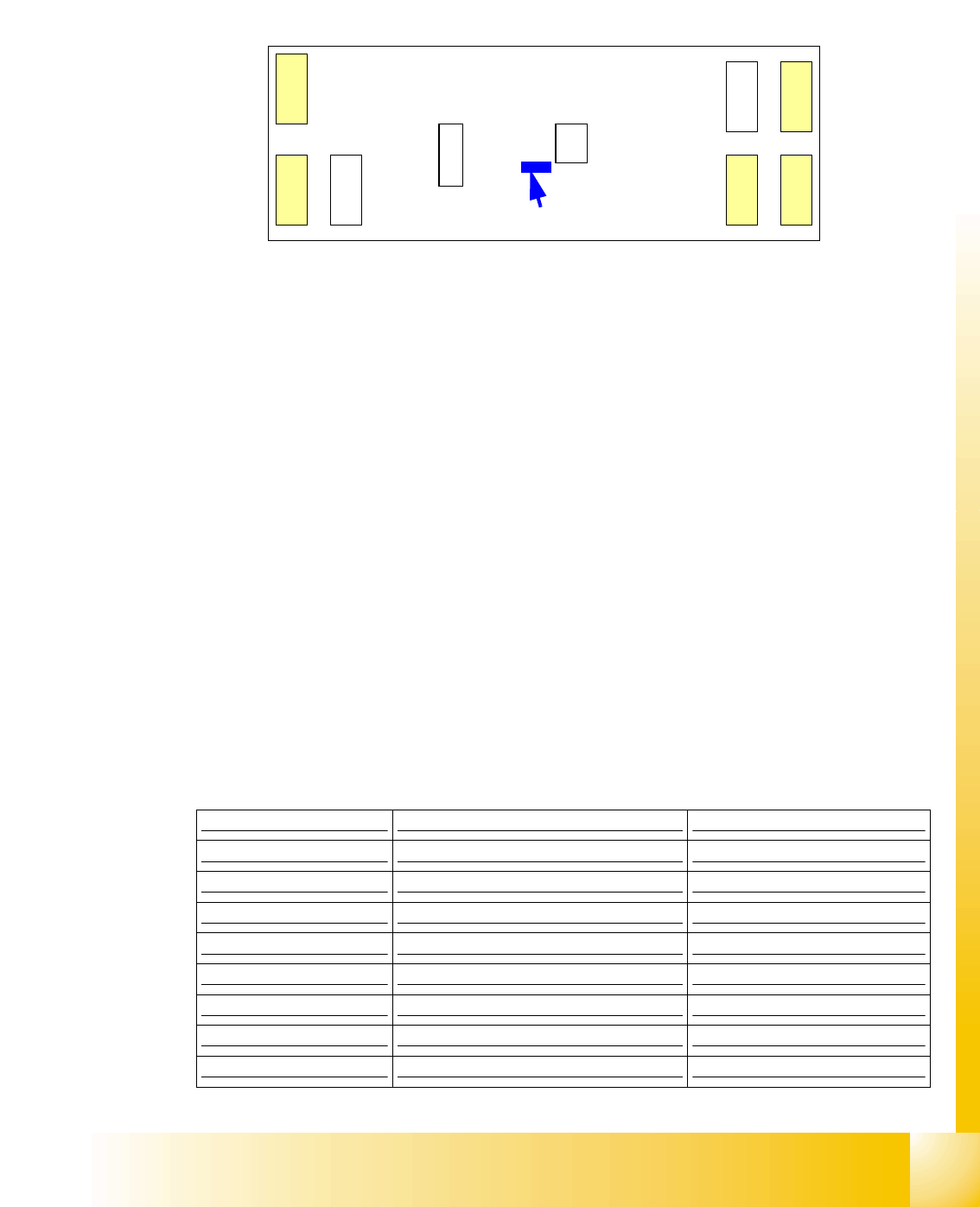
3.3.9.1 Connector on I/O module
Fig. 3.3 - 20 overview CAN I/O module
Legend:
(1) DIP Switches
X1 CAN interface connector and
RS232 analog interface, bootstraploader interface connector
X3, X4, X5 digital inputs 24V
X6 power supply 5V
X7, X8 digital outputs 24V
X9 power supply 24V
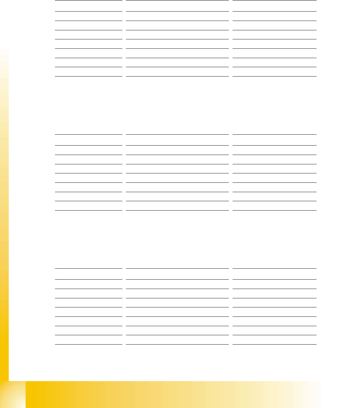
3.3.9.2 CAN I/O module sector 2, main distributor
each connector consist of 8 digital in/outputs
Connector X3qb (input) 3
X7
X
1
R
S
2
3
2
X3, X4, X5 digital input
X7, X8 digital output
CAN I/O module
X
8
X
9
X
3
X
4
X
6
X
5
(1)
X3qb Input
Pin 1 Emergency stop loop o.k. D0
Pin 2 M_emergency stop button D1
Pin 3 M_cover D2
Pin 4 M_component flap D3
Pin 5 M_component table 1 D4
Pin 6 M_component table 2 D5
Pin 7 M_component table 3 D6
Pin 8 M_component table 4 D7
1 - 24
Student Guide SIPLACE HF/HF3
3 Communication and Control Edition 09/2005
24
3
Connector X4qb
(input) 3
Connector X5qb (input) nozzle changer 2 and 3 3
connector X7qb (output) 3
X4qb Input
Pin 1 not used D8
Pin 2 M_ready D9
Pin 3 M_pressure sensor VHS D10
Pin 4 M_gantry crash gantry 1 D11
Pin 5 M_temperature to high D12
Pin 6 M_control On 1 D13
Pin 7 M_key switch 2 D14
Pin 8 M_component table 3 D15
X5qb Input
Pin 1 M_nozzle left (open) A D16
Pin 2 M_nozzl right (closed) A D17
Pin 3 M_nozzle left (open) B D18
Pin 4 M_nozzle right (closed) B D19
Pin 5 M_nozzle left (open) A D20
Pin 6 M_nozzle right (closed) A 1 D21
Pin 7 M_nozzle left (open) B D22
Pin 8 M_nozzle right (closed) B 3 D23
X7qb Output
Pin 1 security message OK D0
Pin 2 software crelease D1
Pin 3 Ctrl_pressure VHS D2
Pin 4 Ctrl. pressure RV/Twin D3
Pin 5 Ctrl_component counter D4
Pin 6 not used D5
Pin 7 trigger LP2 D6
Pin 8 trigger Be2 D7