SG_FSE_SiplaceHF_HF3_00193901-05_eng.pdf - 第98页
1 - 28 S tudent Guide SIPLACE HF/HF3 3 Communication and Control Edition 09/2005 28 I/O Module Main Distributor: (Input s) 3 Connectors I / O Description / Note X3_1 Di0 M_E-Stop Loop1ok or M_Security Loop( "high&qu…
1 - 27
Student Guide SIPLACE HF/HF3
Edition 09/2005 3 Communication and Control
27
3.3.10 CAN I/O Module (SLIO) HF from MA.No. xx
Two CAN Bus I/O modules are integrated in the different section of the HF machine. Both modules
are fully identical
Product characteristics:
– micro controller with integrated CAN controller
– data memory
– programm memory (flash)
– CAN interface with 9 pin connector and address alignment
– 16 digital Output 24 V with status LED
– 24 digital Input 24 V with status LED
– download interface
– power supply 5 V and 24 V
– extended Board on the I/O Module for "One Wire Bus"
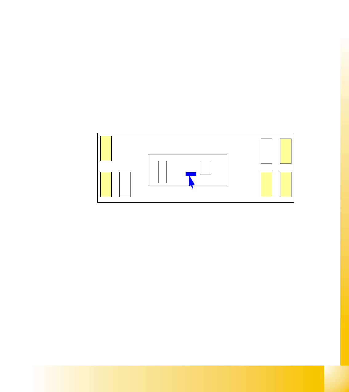
Fig. 3.3 - 21 overview CAN I/O module
Legend
(1) DIP switches ONE Wire board have Paßtrough connectors for
CAN-Bus and RS 232.
X1 CAN-Interface on "ONE Wire Board" RS232 analog interface, bootstraploader inter-
face
X3, X4, X5 digital inputs 24V X6 power supply 5V
X7, X8 digital outputs 24V X9 power supply 24V
X
7
X
1
R
S
2
3
2
X3, X4, X5 digital input
X7, X8 digital output
CAN I/O module
X
8
X
9
X
3
X
4
X
6
X
5
One Wire
Board
(1)
1 - 28
Student Guide SIPLACE HF/HF3
3 Communication and Control Edition 09/2005
28
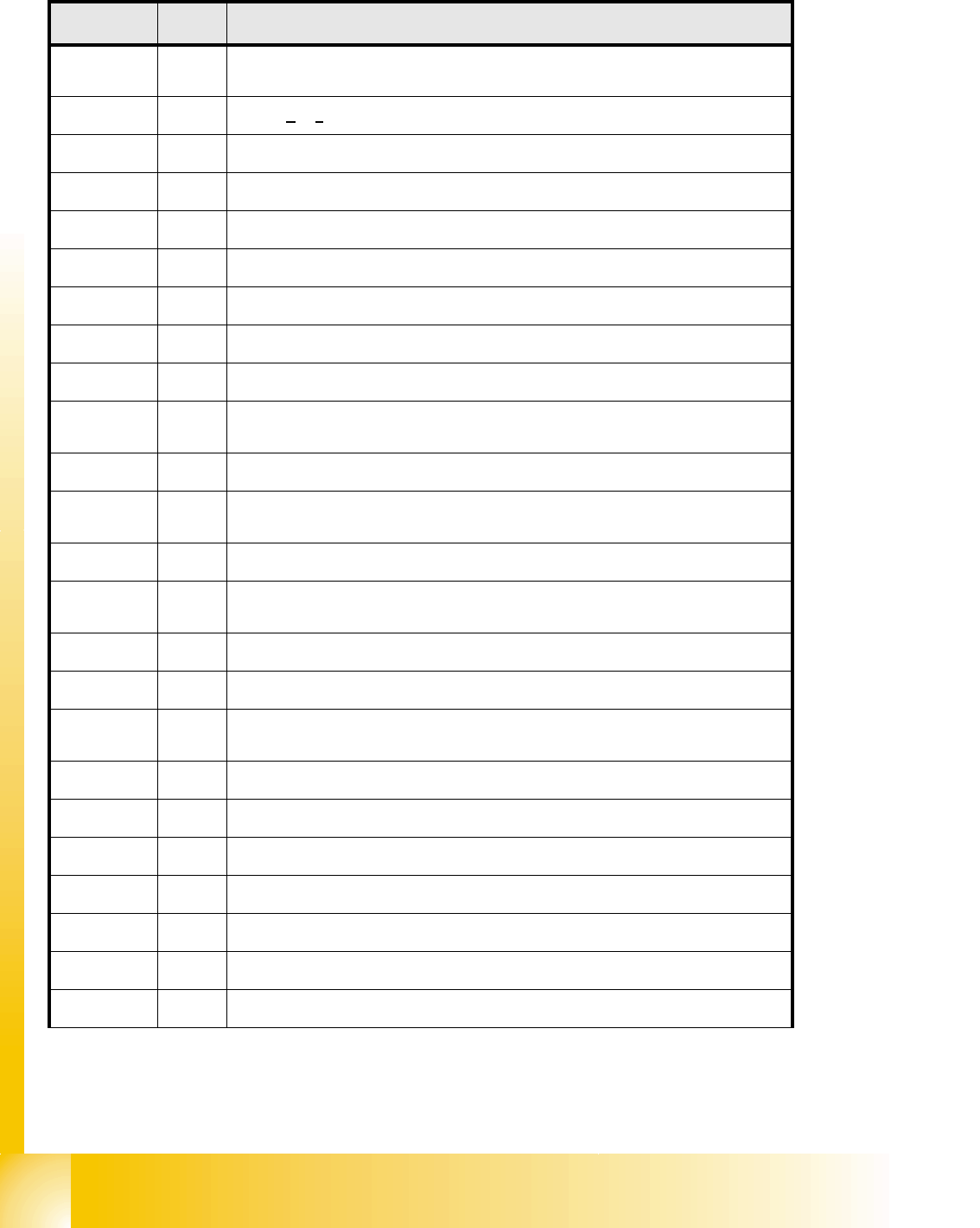
I/O Module Main Distributor: (Inputs) 3
Connectors I / O Description / Note
X3_1 Di0
M_E-Stop Loop1ok or M_Security Loop(
"high" signal if all safety loops closed
(Covers, E-Stop Buttons, Feeder flaps, COT‘s).
X3_2 Di1
nc is
not connected (Reserved)
X3_3 Di2
nc
X3_4 Di3
M_Feeder Flaps (
"high"signal if one or more flaps open.)
X3_5 Di4
nc
X3_6 Di5
nc
X3_7 Di6
nc
X3_8 Di7
nc
X4_1 Di8
nc
X4_2 Di9
M_Ready / This message is changed from
"low" to "high" if the SSK (K6)
latched, only possible if "Control ON".
X4_3 Di10
M_Pressure sensor (reserved)
X4_4 Di11
M_GantryCrash1
"low" Signal gantry 1 and 4 to close , "high" Signal normal
status
X4_5 Di12
nc
X4_6 Di13
M_ServoEnable1 or Control ON /
"high" Signal - intermediate circuit voltage
for X/Y Servo on Axis Unit1 goes through.(K4 message)
X4_7 Di14
nc
X4_8 Di15
M_Pressure sensor C&P/Twin Head
"high" Signal if pressure level reached
X5_1 Di16
M_E-Stop Loop2ok or M_Security Loop(
"high" signal if all safety loops closed
(Covers, E-Stop Buttons, Feeder flaps, COT‘s).
X5_2 Di17
M_Cover2
"high" Signal if the cover2 closed
X5_3 Di18
M_COT2
"high" Signal if the COT 2 connected
X5_4 Di19
M_Cover PCB Output conveyer /
"high" Signal if the cover closed.
X5_5 Di20
M_E-Stop buttonPCBOutput
"high" Signal if the E-Sopt unlocked.
X5_6 Di21
M_Cover3
"high" Signal if the cover3 closed.
X5_7 Di22
M_COT3
"high" Signal if the COT 3 connected
X5_8 Di23
nc
1 - 29
Student Guide SIPLACE HF/HF3
Edition 09/2005 3 Communication and Control
29
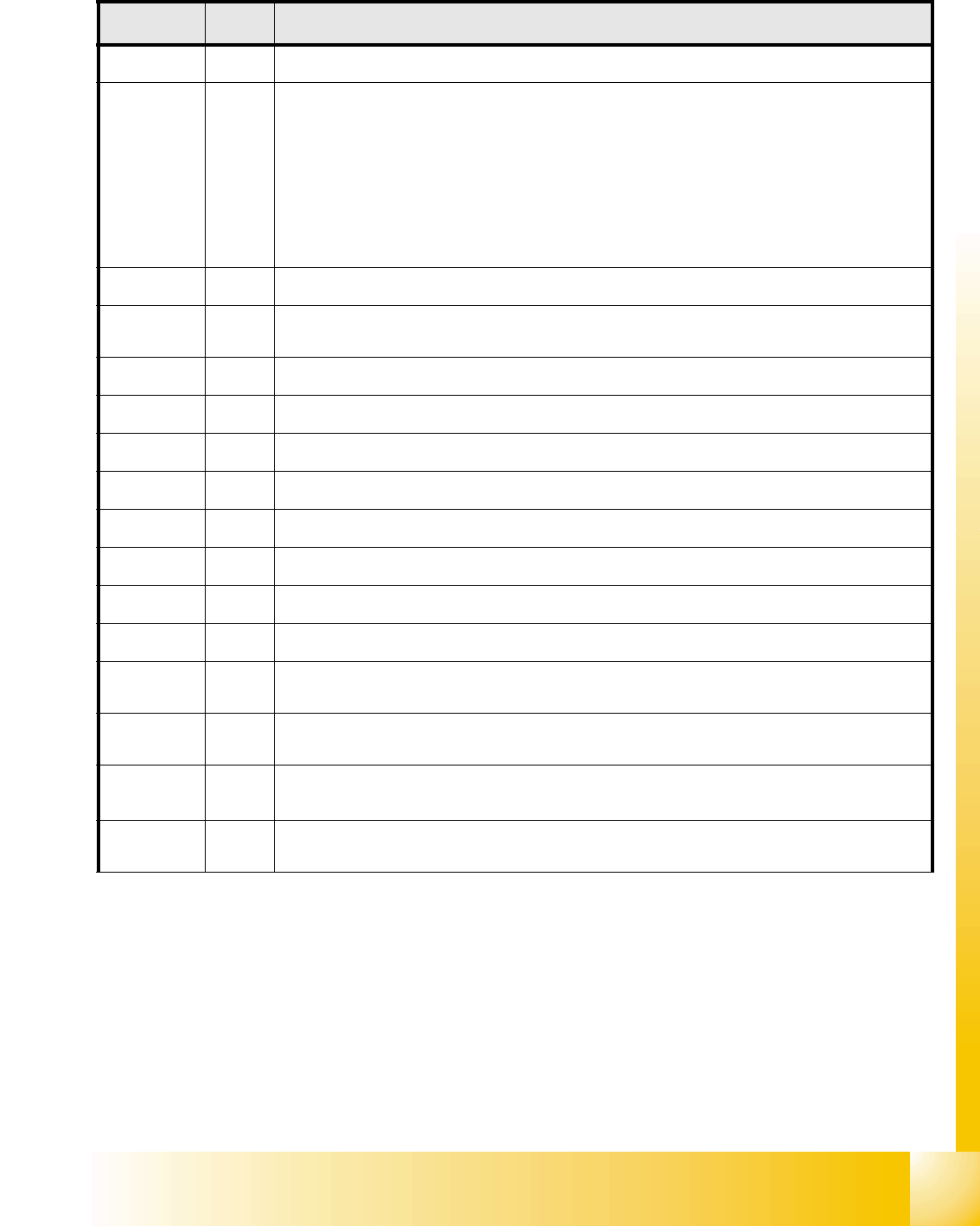
I/O Modul Main Distributor: (Outputs) 3
3
Connectors I / O Description / Note
X7_1 Do0
nc
X7_2 Do1
Ctrl_ON or Software release Only if on Port a "high"-Signal (24V) permanently, then you
can start the machine. The message M_Ready changed from "low" to "high" (EA1/
Di9),if Relay K5 latched. These contacts switch the power supply 24V, the safety loop
1and the Start-buttons on the SSK(K6). When all 6 covers closed, all 4 Feeder flaps,
the two E-Stop buttons and all COT‘s connected, can you press the Start-button and
the SSK is latched. The SSK operate:1.dthe relay K2, K3 and K4 ON and with the
time delay the intermediate circuit voltage for the X-, Y- und Star-Servo boards. 2.the
power supply 24V, 3. the pressure air (Valve) for the tape cutter.4.the two safety loops
for the MTC‘s 5.the power supply for the conveyor motors ON.
X7_3 Do2
Ctrl_pressure air (Reserved)
X7_4 Do3
St_pressure air C&P/Twinpressure OFF (If ON "low" Signal opened the pressure main
valve. A "high" Signal closed this.
3
X7_5 Do4 St_Component Counter / each "high" -Impuls added the counter to one.
X7_6 Do5
nc
X7_7 Do6
nc
X7_8 Do7
nc
X8_1 Do8
nc
X8_2 Do9
nc
X8_3 Do10
nc
X8_4 Do11
nc
X8_5 Do12
St_green light 1 / The right green light of the fault indicator lamp flashed if an
"high" signal on
the port output. Definition: Flashed when no PCB board in the right conveyor lane.
X8_6 Do13
St_white light 1 / The right white light of the fault indicator lamp flashed if an "high"
signal on the port output. Definition: Fault on a feeder on location 1 or 2.
X8_7 Do14
St_white light 2/ The left white light of the fault indicator lamp flashed if an
"high" signal on
the port output. Definition: Fault on a feeder on location 3 or 4.
X8_8 Do15
St_green light 2/ The left white light of the fault indicator lamp flashed if an
"high" signal on
the port output. Definition: Flashed when no PCB board in the left conveyor lane.