Horizon APiX Appendix Manual-low res.pdf - 第29页
INSTALLATION APPENDIX COVERS 2.10 Appendix to Micron Technical Manuals Chapter Issue 1 June 15 Front Corner Panels T o remove the front corner panels, carry o ut the following: 1. Raise the front printhead cover . 2. Rem…
INSTALLATION APPENDIX
COVERS
Chapter Issue 1 June 15 Appendix to Micron Technical Manuals 2.9
COVERS
Rear Corner
Panels
To remove the rear corner panels, carry out the following:
1. Raise the rear printhead cover.
2. Remove the rear panel.
3. Gain access to the rear of the EMO switch.
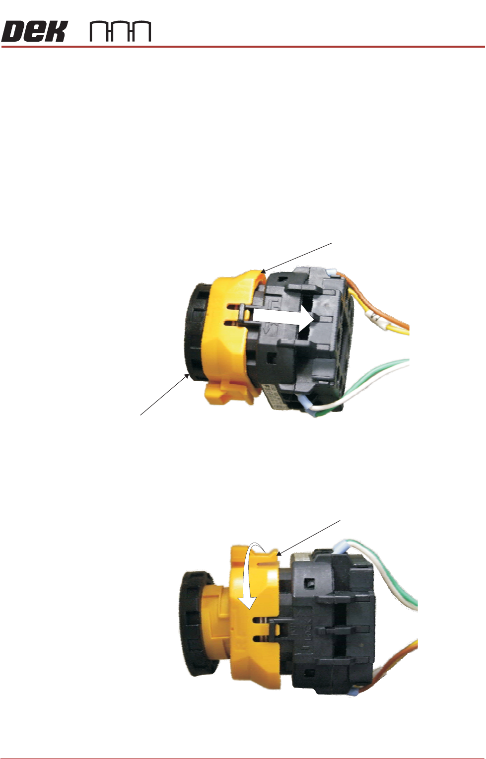
4. To disconnect the EMO carry out the following:
a. Locate the yellow locking collar at the rear of the switch.
b. Slide the collar rearwards towards the switch contact assembly against
spring pressure.
c. Viewed from the rear of the switch, rotate the locking collar anticlockwise
to release the contact assembly from the switch body.
5. Remove the rear corner panel.
Locking Collar
EMO Switch
View on Rear EMO Switch
View on Rear EMO Switch
Locking Collar
INSTALLATION APPENDIX
COVERS
2.10 Appendix to Micron Technical Manuals Chapter Issue 1 June 15
Front Corner
Panels
To remove the front corner panels, carry out the following:
1. Raise the front printhead cover.
2. Remove the front panel.
3. Gain access to the rear of the EMO switch.
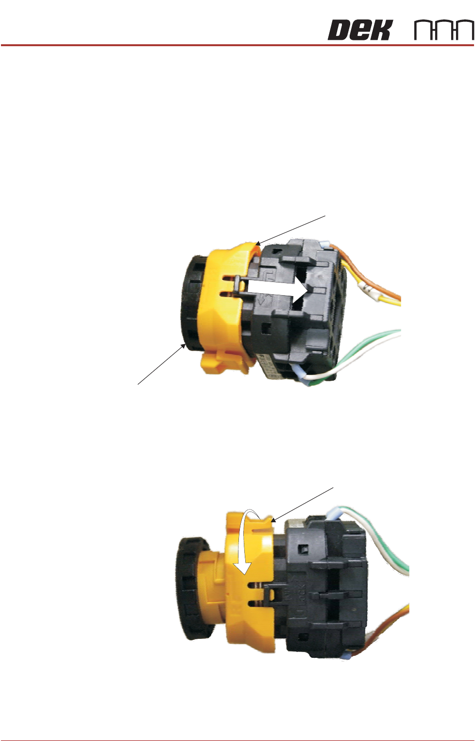
4. To disconnect the EMO carry out the following:
a. Locate the yellow locking collar at the rear of the switch.
b. Slide the collar rearwards towards the switch contact assembly against
spring pressure.
c. Viewed from the rear of the switch, rotate the locking collar anticlockwise
to release the contact assembly from the switch body.
5. Remove the front corner panel.
Locking Collar
EMO Switch
View on Rear EMO Switch
View on Rear EMO Switch
Locking Collar
INSTALLATION APPENDIX
EXTERNAL SERVICES
Chapter Issue 1 June 15 Appendix to Micron Technical Manuals 2.11
EXTERNAL SERVICES
Pneumatic Supply The machine requires a pneumatic supply of clean, non lubricated air which
should maintain a minimum pressure of 5 Bar and a maximum of 7 Bar.
The air should be to ISO 8573.1 standard, quality class 2.3.3, where:
• 2 dirt = 1 micron
• 3 water = -20°C pressure dewpoint
• 3 oil = 1mg/m3
If an emergency stop is initiated via an EMO push button switch, the pneumatic
supply is closed off and any pressurised air remaining within the machine’s
system is vented via the pneumatic dump valve.
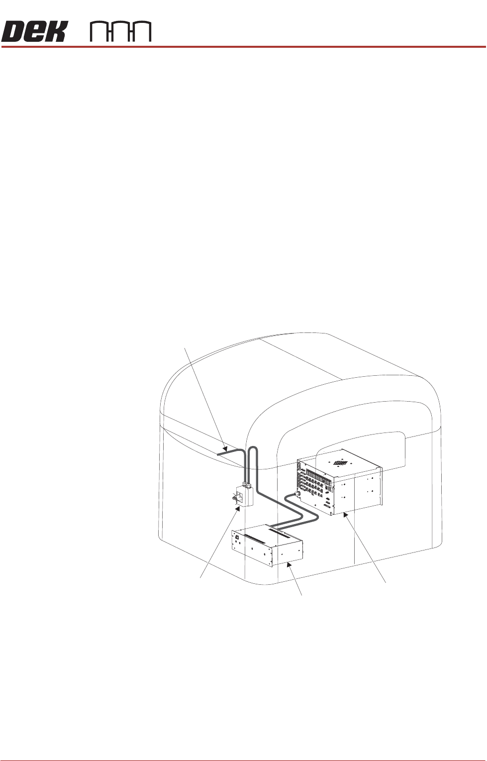
Electrical Supply The factory mains supply for the machine is routed through the front panel
mounted mains isolator switch to the M39 EMO enclosure. If both EMO push
button switches are de-activated and the Start button has been pressed mains
voltage is applied to the M37 power supply enclosure. From the enclosure
various low voltages are distributed throughout the machine.
Figure 2-3 Mains Electrical Supply
The machine operates on 115V or 230V± 10% 50/60Hz single phase ac mains,
current rating 10A or 2.4Kw.
NOTE
The voltage selector of the VF35i vacuum filtration unit needs to be set to the
factory mains supply. This is carried out in the Machine Preparation Chapter of
the Micron Installation Manual.
ASM recommends a power supply capacity of 2.4KVA or greater.
Mains Isolator
Switch
M37 Power
Supply Enclosure
From Factory
Mains Supply
M39 EMO Enclosure