00198158-01_AI_Speed_Config_RV12_NC_EN - 第15页
Speed (Single-Sided) DLM-RV12 - Option 1 Installation Procedures Assembly Instructions E by SIPLACE 15 ► Place th e "Height me asurement b lock SPEED" [03119428 xx] onto t he shim cover and move the head holder…
Speed (Single-Sided) DLM-RV12 - Option 1
Installation Procedures
14 Assembly Instructions E by SIPLACE
2.1
2.1 Installation Procedures
Installation Procedures
► Mount "Nozzle station support" [03105456-xx] onto "NC mounting bracket FLEX 1 Left" [03109945-
xx] using two M4x10 countersunk screws.
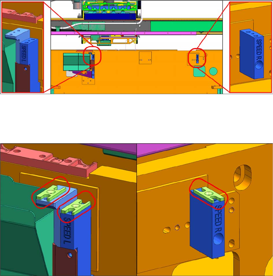
► Mount "NC mounting bracket SPEED right" [03108035-xx] onto the machine base frame using an
M5x30 cap screw.
► Mount one shim cover [03108393 xx] each on "NC mounting bracket Speed left" [03108126 xx] and
"NC mounting bracket Speed" right [03108035 xx].
Speed (Single-Sided) DLM-RV12 - Option 1
Installation Procedures
Assembly Instructions E by SIPLACE 15
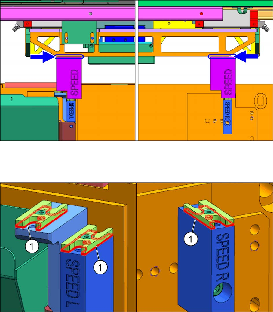
► Place the "Height measurement block SPEED" [03119428 xx] onto the shim cover and move the
head holder manually toward the block with care.
► Use a feeler gauge to determine the gap and the number of "NC shims" [03108395 xx] required.
► Place the required shims (1) underneath the shim cover and fasten them with an M3x8 countersunk
screw.
Speed (Single-Sided) DLM-RV12 - Option 1
Installation Procedures
16 Assembly Instructions E by SIPLACE
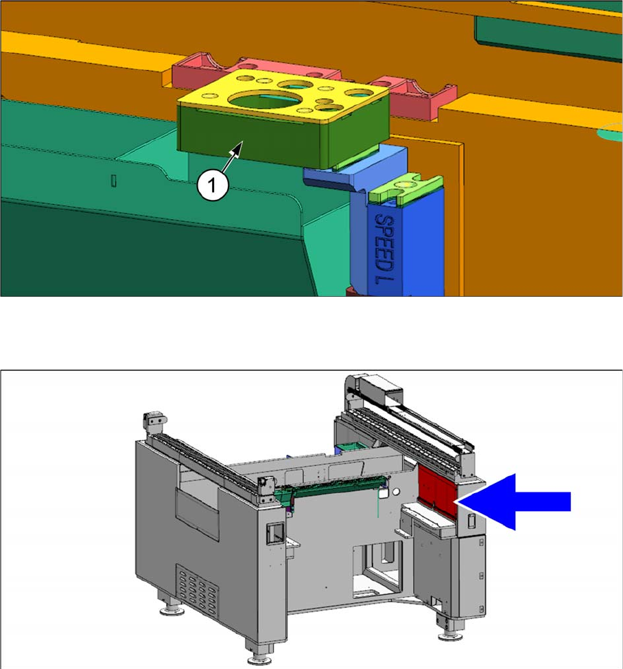
► Place the "Reject Device" [03109608-xx] (1) onto the shim cover after the height has been adjusted
and secure it with two M4x20 countersunk screws.
► Remove the red cover shown and locate the nozzle changer control cable [03102710
-
xx].