00198158-01_AI_Speed_Config_RV12_NC_EN - 第29页
Speed (Double-Sided) DLM-RV12 - Option 2 Installation Procedures Assembly Instructions E by SIPLACE 29 ► Place th e "NC single row for D LM4 RV6/12, C&P14 P" [ 03106322 - xx ] o nt o t h e s h i m c o v e r…
Speed (Double-Sided) DLM-RV12 - Option 2
Installation Procedures
28 Assembly Instructions E by SIPLACE
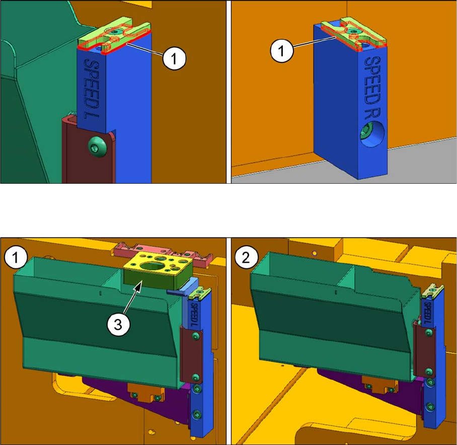
► Place the required shims (1) underneath the shim cover and fasten them with an M3x8 countersunk
screw.
The machine can only accommodate one nozzle station (3) in location 1 (1). There is no nozzle station
in location 2 (2).
The reject bin in location 1 collects both rejected components and rejected nozzles. The reject bin in lo
-
cation 2 reject bin only collects rejected components.
Speed (Double-Sided) DLM-RV12 - Option 2
Installation Procedures
Assembly Instructions E by SIPLACE 29
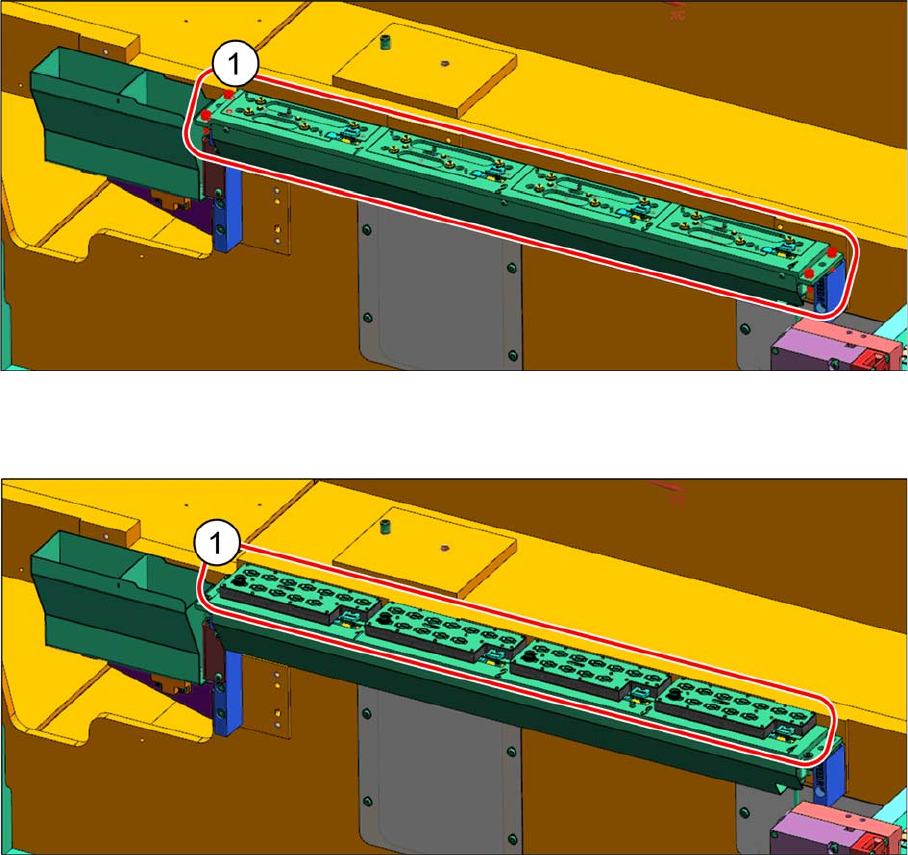
► Place the "NC single row for DLM4 RV6/12, C&P14 P" [03106322
-
xx] onto the shim covers and fas
-
ten it with four M5x14 cap screws.
► Install the active nozzle magazines (1).
Speed (Double-Sided) DLM-RV12 - Option 2
Installation Procedures
30 Assembly Instructions E by SIPLACE
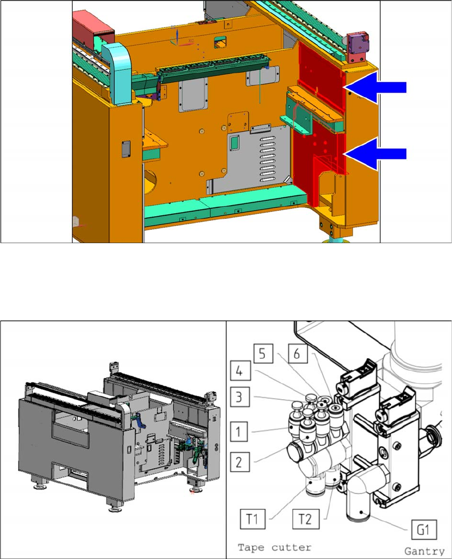
► Remove the red covers shown and locate the nozzle changer control cable [03109999
-
xx] and the
connectors to the cable of the nozzle changer "NC single row for DLM 4 RV6/12, C&P14 P"
[03106322
-
xx].
► Connect the 6 mm diameter tube "Tube Nozzle Changer LOC2" [03102150
-
xx] to port 4 of the air
service unit in location 2. Port 4 is the port shown in the picture.