TR7500_Hardware_en - 第12页
11 F i g u r e 1 . 2 3 S t a r t T e s t 1 . 3 . 4 . 4 . BA C K : R e t u r n t o t h e F i gu r e 1 . 5 O T H E R S s e t t i n g p a ge . 1 . 3 . 4 . 5 . B Y P ASS (F i g u r e 1 . 2 4 ) : C on f i r m t ha t i f t h e…
10
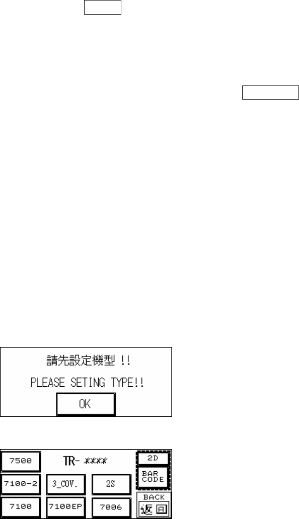
u Type Setting: There are currently Five machine types, if this is the first time a
new machine has been set up, the Figure 1.21 display will be shown at the
start for the machine type to be set. Use Figure 1.22 to set the machine type.
Once setting is done, to change the settings again at the Figure 1.20
Language selection display there are two hidden buttons on either side, press
both simultaneously to jump to the Figure 1.22 display to make the selection.
Once setting is complete the TR-**** position in Figure 1.22 and Figure 1.23
will show the set machine type.
u Barcode Sampling Setting: This setting is used to stop board loading if
reading of the barcode fails. If this function is not used please set the PC
software to not sample the barcode, or press to highlight the BARCODE in
Figure 1.22, otherwise the board won’t load.
u 2D Barcode: If 2D Barcode is used, 2D needs to be highlighted. .
u Dual Screw Conveyor Belt: If the conveyor belt uses dual screws, 2S needs to
be highlighted.
u Three Stage Conveyor Belt: If the conveyor belt uses three stages, the 3_COV.
needs to be highlighted.
*If it is a single stage conveyor belt then this setting must not be selected or the
PLC may crash. If a crash occurs, reset the main power and then deselect this
setting.
Figure 1.21 Initial Startup Display
Figure 1.22 Set Machine Type
11
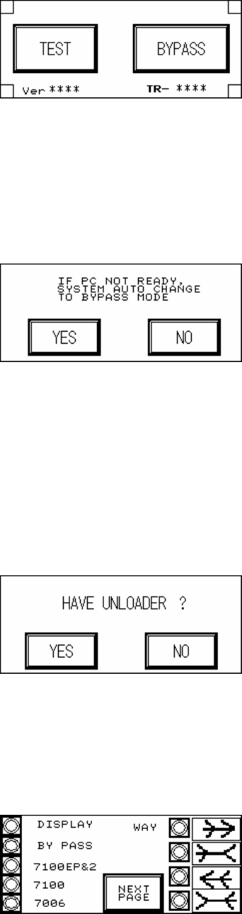
Figure 1.23 Start Test
1.3.4.4. BACK: Return to the Figure 1.5 OTHERS setting page.
1.3.4.5. BYPASS (Figure 1.24): Confirm that if the PC is not ready, the PLC will automatically
change to Bypass Mode to avoid Loader blockage.
Figure 1.24 BYPASS
1.3.4.6. BACK: Go back to the Figure 1.1 starting screen.
1.3.5 UNLOADER (Figure 1.25): Choose if there is an Unloader. In Inline mode, once test is
completed and the Unloader sends a READY signal then the board will automatically be
unloaded. If there is no Loader, once the test is completed the board will stop at the exit
and wait for manual removal before processing the next board.
Figure 1.25 UNLOADER
1.3.6 BACK: Go back to the Figure 1.1 starting screen.
1.4 DISPLAY: Through Figure 1.26 and Figure 1.27 all of the currently set mode parameters
can be viewed.
Figure 1.26 Display 1
12
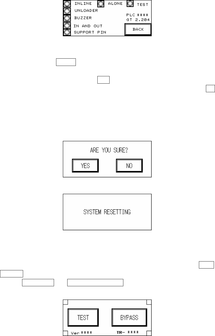
Figure 1.27 Display 2
1.5 RESET: After pressing RESET the screen will show a confirmation dialog. Once reset has
been completed testing will begin.
1.5.1 RESET Confirmation (Figure 1.28): If YES is pressed then the Reset operation will be
executed, and the display will show that the system is resetting (Figure 1.29); if NO is
pressed then it will return to the previous display. Upon the initial power up of the machine
or after an emergency system shutdown, the Reset action will return the X-Y Table to the
original position and move the PCB to the unload end (depending on the direction set). In
other situations the X-Y Table will not move but the PCB will still be moved to the unload
end.
Figure 1.28 Confirm Reset
Figure 1.29 System Resetting
1.5.2 Start TEST (Figure 1.30, Figure 1.31, Figure 1.32): Once the system reset has been
completed, if the mode is set to Inline then the display will show two options: TEST and
BYPASS (Figure 1.30); if the mode is set to Stand-Alone mode then the display will two
options: single TEST and CONTINUOUS TEST (Figure 1.31); if the mode is set to TEST
mode, then the display will show only the start TEST option (Figure 1.32).
Figure 1.30 Inline mode