TR7500_Hardware_en - 第13页
12 F i g u r e 1 . 2 7 D i s p l a y 2 1 . 5 R ES E T : A f t e r p r e ssi ng R ESE T t he s c r e en w i ll s h o w a c on f i r m a t i o n d i a l o g . O n c e r e s e t h a s be e n c o m p l e t ed t e s t i n g w…
11
Figure 1.23 Start Test
1.3.4.4. BACK: Return to the Figure 1.5 OTHERS setting page.
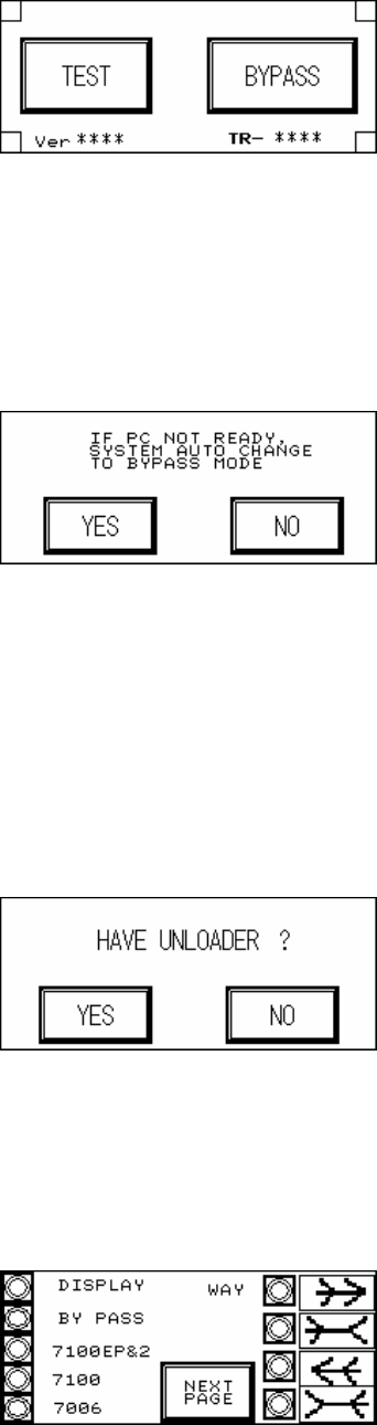
1.3.4.5. BYPASS (Figure 1.24): Confirm that if the PC is not ready, the PLC will automatically
change to Bypass Mode to avoid Loader blockage.
Figure 1.24 BYPASS
1.3.4.6. BACK: Go back to the Figure 1.1 starting screen.
1.3.5 UNLOADER (Figure 1.25): Choose if there is an Unloader. In Inline mode, once test is
completed and the Unloader sends a READY signal then the board will automatically be
unloaded. If there is no Loader, once the test is completed the board will stop at the exit
and wait for manual removal before processing the next board.
Figure 1.25 UNLOADER
1.3.6 BACK: Go back to the Figure 1.1 starting screen.
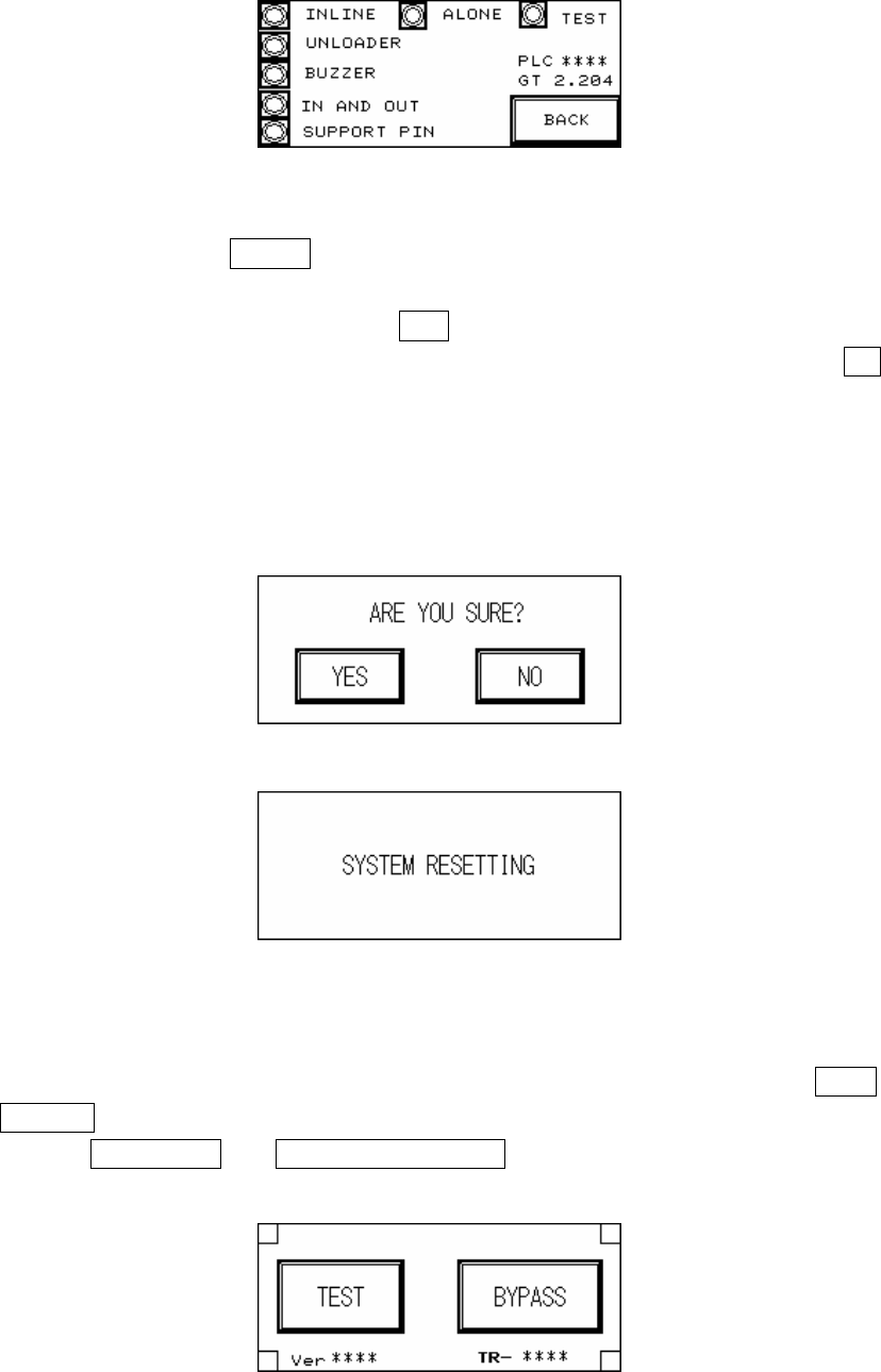
1.4 DISPLAY: Through Figure 1.26 and Figure 1.27 all of the currently set mode parameters
can be viewed.
Figure 1.26 Display 1
12
Figure 1.27 Display 2
1.5 RESET: After pressing RESET the screen will show a confirmation dialog. Once reset has
been completed testing will begin.
1.5.1 RESET Confirmation (Figure 1.28): If YES is pressed then the Reset operation will be
executed, and the display will show that the system is resetting (Figure 1.29); if NO is
pressed then it will return to the previous display. Upon the initial power up of the machine
or after an emergency system shutdown, the Reset action will return the X-Y Table to the
original position and move the PCB to the unload end (depending on the direction set). In
other situations the X-Y Table will not move but the PCB will still be moved to the unload
end.
Figure 1.28 Confirm Reset
Figure 1.29 System Resetting
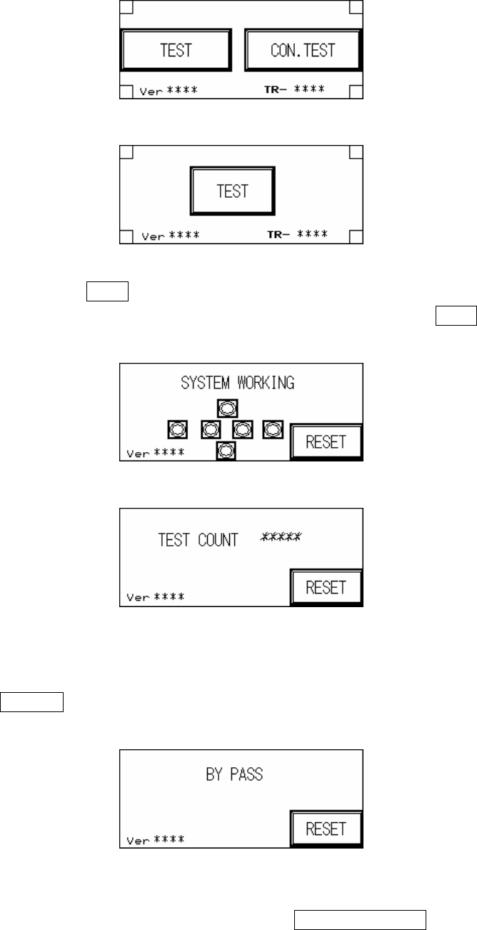
1.5.2 Start TEST (Figure 1.30, Figure 1.31, Figure 1.32): Once the system reset has been
completed, if the mode is set to Inline then the display will show two options: TEST and
BYPASS (Figure 1.30); if the mode is set to Stand-Alone mode then the display will two
options: single TEST and CONTINUOUS TEST (Figure 1.31); if the mode is set to TEST
mode, then the display will show only the start TEST option (Figure 1.32).
Figure 1.30 Inline mode
13
Figure 1.31 Stand-Alone mode
Figure 1.32 Test mode
1.5.2.1. Start TEST: Press TEST under Inline and Stand-Alone mode to begin testing, the display
Figure 1.33 will show that the system has begun AOI testing; press TEST under Test
mode and the display Figure 1.34 will show the number of tests performed so far.
Figure 1.33 System Working
Figure 1.34 Tests Performed
1.5.2.2. INLINE mode: In Inline mode, if the system is malfunctioning or testing is not desired,
press BYPASS to show the Figure 1.35 display. PCB will not be tested and go straight
through to the Unloader.
Figure 1.35 BYPASS Display
1.5.2.3. STAND-ALONE mode: In Stand-Alone mode, if continuous testing is selected, 0.5
seconds after the tested board has been removed and 0.5 seconds after the next board