TR7500_Hardware_en - 第14页
13 F i g u r e 1 . 31 S t an d - A l on e m od e F i gu r e 1 . 3 2 T e s t m o d e 1 . 5 . 2 . 1 . S t a r t T E S T : P r e s s T ES T u nd e r I n l i n e a n d S t a nd - A l on e m od e t o b eg i n t e s t i ng , t…
12
Figure 1.27 Display 2
1.5 RESET: After pressing RESET the screen will show a confirmation dialog. Once reset has
been completed testing will begin.
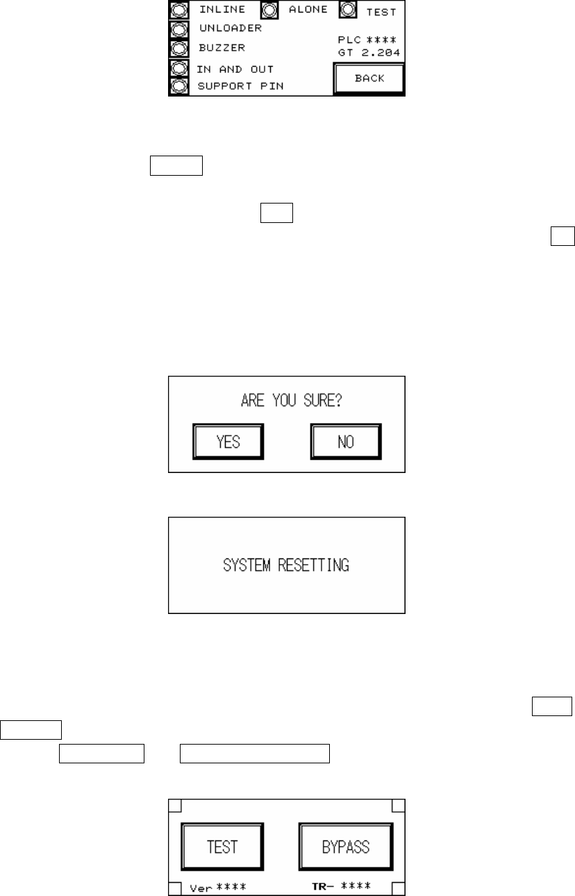
1.5.1 RESET Confirmation (Figure 1.28): If YES is pressed then the Reset operation will be
executed, and the display will show that the system is resetting (Figure 1.29); if NO is
pressed then it will return to the previous display. Upon the initial power up of the machine
or after an emergency system shutdown, the Reset action will return the X-Y Table to the
original position and move the PCB to the unload end (depending on the direction set). In
other situations the X-Y Table will not move but the PCB will still be moved to the unload
end.
Figure 1.28 Confirm Reset
Figure 1.29 System Resetting
1.5.2 Start TEST (Figure 1.30, Figure 1.31, Figure 1.32): Once the system reset has been
completed, if the mode is set to Inline then the display will show two options: TEST and
BYPASS (Figure 1.30); if the mode is set to Stand-Alone mode then the display will two
options: single TEST and CONTINUOUS TEST (Figure 1.31); if the mode is set to TEST
mode, then the display will show only the start TEST option (Figure 1.32).
Figure 1.30 Inline mode
13
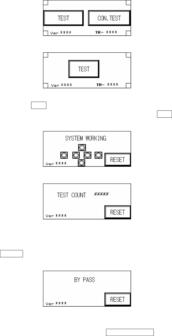
Figure 1.31 Stand-Alone mode
Figure 1.32 Test mode
1.5.2.1. Start TEST: Press TEST under Inline and Stand-Alone mode to begin testing, the display
Figure 1.33 will show that the system has begun AOI testing; press TEST under Test
mode and the display Figure 1.34 will show the number of tests performed so far.
Figure 1.33 System Working
Figure 1.34 Tests Performed
1.5.2.2. INLINE mode: In Inline mode, if the system is malfunctioning or testing is not desired,
press BYPASS to show the Figure 1.35 display. PCB will not be tested and go straight
through to the Unloader.
Figure 1.35 BYPASS Display
1.5.2.3. STAND-ALONE mode: In Stand-Alone mode, if continuous testing is selected, 0.5
seconds after the tested board has been removed and 0.5 seconds after the next board
14
is inserted, automated loading and testing will run; if single test is selected, when one
board has been tested, then single test must be pressed again to load the next board for
testing (Figure 1.31).
1.5.2.4. Hidden Button Setting: In Figure 1.30, Figure 1.31 or Figure 1.32 at the four corners of
the display there are four hidden buttons. These can be used to jump to the starting page
or the Debug display. If the bottom left and right corner hidden buttons are pressed within
two seconds of each other, then it will jump to the Figure 1.1 starting display. If the top
left and right hidden buttons are pressed within two buttons of each other, then it will
open the Debug display (Figure 2.1).
2. Debug Display: If at the Figure 1.30, Figure 1.31 or Figure 1.32 display the hidden buttons in
the top left and right corner are pressed within two seconds of each other then it will open the
Debug display (Figure 2.1).
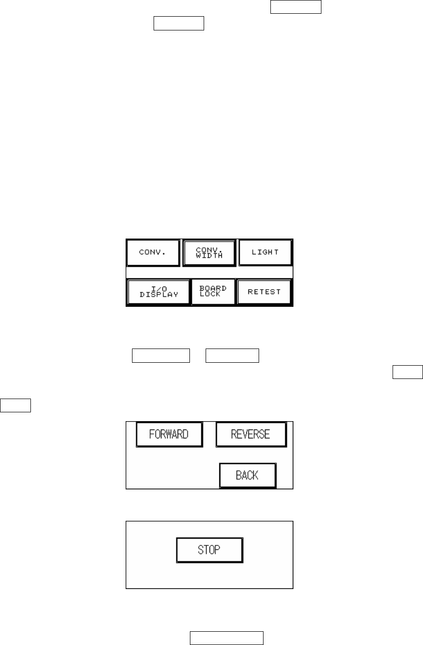
Figure 2.1 DEBUG Display
2.1 CONV. (Figure 2.2): Press FORWARD or REVERSE and the Conveyor belt will
immediately run forwards or in reverse and jump to the Figure 2.3 display. Press STOP and
the conveyor belt will immediately stop and jump back to the Figure 2.2 display; press
BACK to return to Figure 2.1.
Figure 2.2 Forward and Reverse Setting for the Conveyor Belt
Figure 2.3 Stop the Conveyor Belt
2.2 CONV. WIDTH (Figure 1.7): Press the CONV. WIDTH in Figure 2.1 and the Figure 1.7
display will appear. Use the spin wheel to set the conveyor width, and when the setting is