TR7500_Hardware_en - 第20页
19 2 . 5 B O A R D H O L D E R (F i gu r e 2 . 1 4 ) : P r e ss B O A R D L O C K o r B O A RD U N L O C K t o t e s t i f t h e B o a r d H o l d e r i s w o r k i n g n o r m a ll y ; p r e s s BA C K t o r e t u r n t…

18
Table 2.1 I/O(PF2-XY64D2T&PF2-Y16P) Unit
PIN Number
PIN DIFN.
X80(IN) EMS
X87(IN) DRCH RESET DONE(used by TR-7100)
X90(IN) SENSOR1
X91(IN) SENSOR2
X92(IN) SENSOR3
X93(IN) SENSOR4
X94(IN) SENSOR5
X95(IN) SENSOR6
X98(IN) UNLOADER READY (from load - port2 Black-Green)
X9A(IN) TEST OK (from pc)
X9B(IN) PC TEST COMPLETE (from pc)
X9C(IN) PC ABORT (from pc)
X9D(IN) CLEAR NOTIFY PC TEST (from pc)
X9E(IN) 2D LED2(from PC, used by the TR-7006/L)
X9F(IN) LASER ON(from PC, used by the TR-7006/L)
Y100(OUT)
RED LIGHT
Y101(OUT)
YELLOW LIGHT
Y102(OUT)
GREEN LIGHT
Y103(OUT)
BUZZER
Y104(OUT)
REQUEST BOARD FROM LOADER (to unload – Port1
Black-Green)
Y105(OUT)
TEST OK (to unload - port1 Yellow-White)
Y109(OUT)
BARCODE START
Y110(OUT)
START CONVEYOR MOTOR (used by TR-7100)
Y111(OUT) STOP CONVEYOR MOTOR (used by TR-7100)
Y112(OUT)
SLOW CONVEYOR MOTOR (used by TR-7100),
2D LED2 (used by TR-7600/L)
Y113(OUT)
REVERSE CONVEYOR MOTOR (used by TR-7100),
2D LED1 (used by TR-7600/L)
Y114(OUT)
DRCH POWER (used by TR-7100/ TR-7100EP)
Y115(OUT)
DOS PC POWER(used by TR-7100/ TR-7100EP)
Y116(OUT)
BRAKE CONVEYOR WIDTH
Y117(OUT)
NOTIFY PC TEST (used by TR-7100EP/TR7600)
Y118(OUT)
NOTIFY PC EMERGENCY STOP
(used by TR-7100EP/TR7600)
Y119(OUT)
NOTIFY PC READ BARCODE
(used by TR-7100EP/TR7600)
19
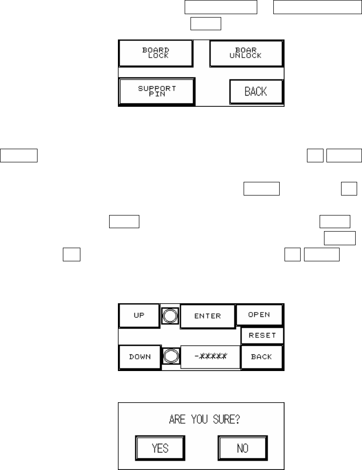
2.5 BOARD HOLDER (Figure 2.14): Press BOARD LOCK or BOARD UNLOCK to test if the
Board Holder is working normally; press BACK to return to the Figure 2.1 Debug display.
Figure 2.14 Board Holder
2.5.1 SUPPORT PIN (Figure 2.15): Place the candidate board at the loading Sensor and press
ENTER. Wait until the Support Pin is in position then press the UP/DOWN button to
gradually adjust it up and down. First it needs to be moved to the lowest position (the
lower limit indicator light will be lit) and then press RESET. Now press UP to adjust it to
the location to support the candidate board as shown in Figure 2.15 below. The setting
value will be shown at -******, and when setting is complete press BACK. If this accessory
was not purchased or not in use, please make sure that you press OPEN and at Figure
2.16 choose NO (or it can not be reset). To the right of the UP/DOWN buttons are their
respective upper and lower elevation limit Sensor indicator lights. If the indicator light is lit,
it means the limit has been reached.
Figure 2.15 Support Pin Setting
Figure 2.16 Confirm to Open the Support Pin Function
2.6 RESET: Press the RESET button to return to the TEST display (Figure 1.30, Figure 1.31 or
Figure 1.32).
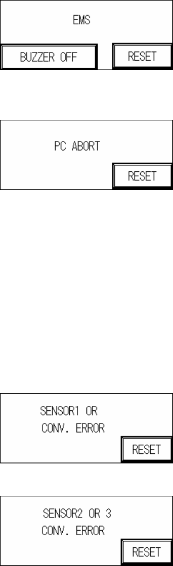
1.3 Human Machine Interface Alert Messages and Causes
1 EMS: Causes as follows.
1.1 Emergency Stop button pressed.
1.2 The door lid or rear lid has been opened. To deactivate this function, set the rocker
20
switch on the inside of the lid to OFF, but please pay attention to safety.
2 PC Aborts Testing: PC sends ABORT signal.
3 Sensor or Conveyor Belt Abnormal Operation
3.1 SENSOR Always On:
3.1.1 The Sensor sensitivity range is too long.
3.1.2 The candidate board has been covering the sensor for too long, there may be a
jam or the conveyor belt may not be operating.
3.2 SENSOR Always OFF:
3.2.1 The Sensor sensitivity range is too short.
3.2.2 The candidate board has not been detected by the sensor for too long, there may
be a jam or the conveyor belt may not be operating.
3.3 Conveyor Error: Motor or Motor Driver Malfunctioning, or Belt Detached.
Sensor 1 Error
Sensor 2 or 3 Error