TR7500_Hardware_en - 第22页
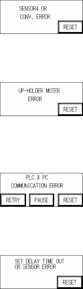
21 S e n s o r 4 E r r o r 4 H o l d e r M o t o r E r r o r 4 . 1 S e n s o r 5 o r 6 , O N/ O FF e rr o r : I n c o rr e c t d e t e c t i o n h e i g h t a d j u s t m en t . 4 . 2 Mo t o r E rr o r : Mo t o r o r Mo …
20
switch on the inside of the lid to OFF, but please pay attention to safety.
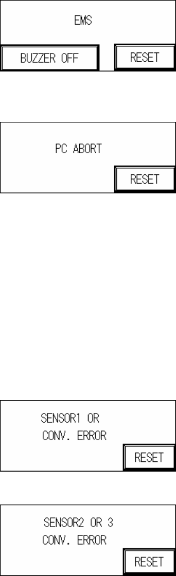
2 PC Aborts Testing: PC sends ABORT signal.
3 Sensor or Conveyor Belt Abnormal Operation
3.1 SENSOR Always On:
3.1.1 The Sensor sensitivity range is too long.
3.1.2 The candidate board has been covering the sensor for too long, there may be a
jam or the conveyor belt may not be operating.
3.2 SENSOR Always OFF:
3.2.1 The Sensor sensitivity range is too short.
3.2.2 The candidate board has not been detected by the sensor for too long, there may
be a jam or the conveyor belt may not be operating.
3.3 Conveyor Error: Motor or Motor Driver Malfunctioning, or Belt Detached.
Sensor 1 Error
Sensor 2 or 3 Error
21
Sensor 4 Error
4 Holder Motor Error
4.1 Sensor 5 or 6, ON/OFF error: Incorrect detection height adjustment.
4.2 Motor Error: Motor or Motor Driver malfunction.
Up-Holder Motor Error
5 PC & PLC Communication Error: The candidate board has been locked and the PC notified
to commence testing. No action taken within 10 seconds of the notification.
5.1 PC & PLC communication link malfunction.
5.2 PC program not being executed or malfunctioning.
PC & PLC Communication Error
6 Speed Reduction Error: When the loading speed is too fast or Sensor 1 and Sensor 2 are
located too closely together, speed reduction may not occur in time so this measure is
triggered to prevent board from falling off.
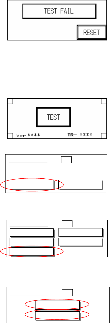
7 Board Test Fail: When the test results in a Fail, the PC will send a FAIL signal. A confirmation
from the PC is required before it can return to the system’s operational display.
22
1.4 Human Machine Interface Program Replacement
l Before replacing the PLC and HCI program the original files must be purged. The steps are
as follows:
Step 1 : At the Start Test display press down on four corners of the HCI.
Step 2 : At the display, press Setting.
Step 3 : Press Memory.
Step 4 : Press [SRAM] and [FROM] to purge the Memory.
u Human Machine Interface Program Update Process is as follows:
Step 1: First connect the PLC-PC data cable properly, with the PS2 connector connected to
the rear of the PCI, and the RS232 connected to Main PC COM1.
Step 2: Open the Program Files’ GTWIN (as shown in the figure below)
■System Menu ESC
System Ver 2.02
Setting
Test
■System Menu ESC
Clock
Contrast
Memory
TOOL Port
COM. Port
■System Menu ESC
SRAM
FROM